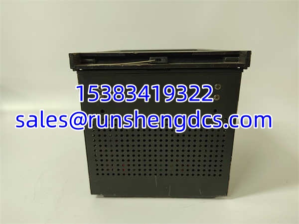

Description
Key Technical Specifications
| Parameter | Specification |
|---|---|
| Model Number | SR469-P5-HI-A20 |
| Brand | GE Multilin |
| Product Type | Motor Management Relay |
| CT Rating | 5A phase CT secondaries |
| Control Power (P5) | 85–265 VAC or 90–300 VDC (universal) |
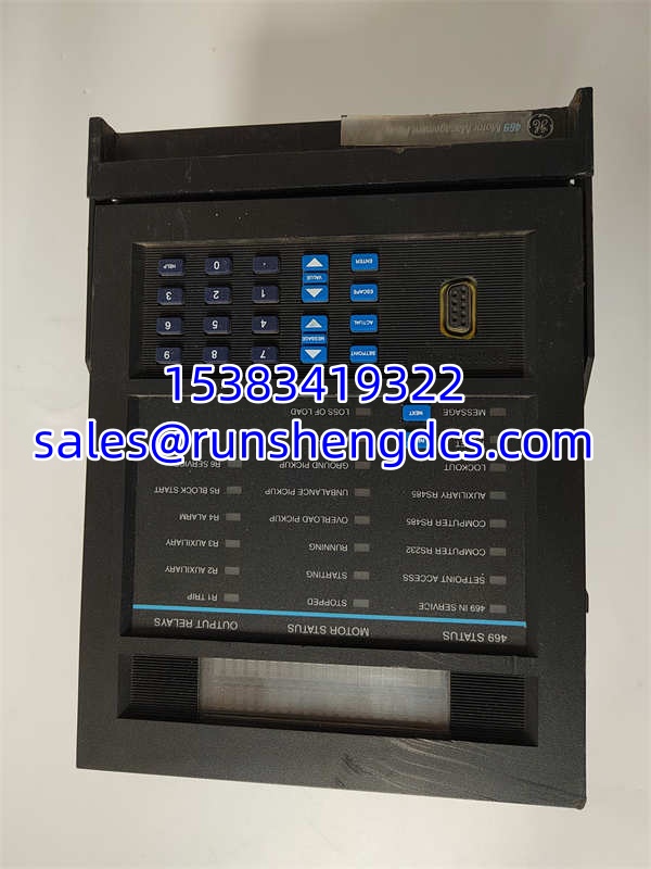
| Front Panel (HI) | Enhanced HMI — 40-character LCD, dedicated alarm/trend/setpoint keys |
| Analog Outputs (A20) | Isolated 4–20 mA (motor current, thermal capacity, kW retransmission) |
| RTD Inputs | Up to 12 channels (Pt100 / Ni120) |
| Communication | RS-485 (Modbus RTU), front RS-232 service port (9600 baud, programmable to 19200) |
| Protection Functions | Thermal overload, jam/stall, phase loss/unbalance, negative sequence, ground fault, starts-per-hour, start supervision |
| Operating Temperature | -20°C to +60°C (typical) |
| Storage Temperature | -40°C to +80°C |
| Humidity | Up to 95%, non-condensing |
| Output Relay Operate Time | ~10 ms |
| Mounting | Panel-door mount in MCC/switchgear (cutout approx. 192 × 192 mm) |
| Weight | Approx. 2.2 kg |
| Dimensions | Approx. 230 × 165 × 80 mm |
Product Introduction
Medium-voltage motor protection used to require a stack of discrete relays — one for overcurrent, one for ground fault, one for thermal, another for unbalance. The SR469 collapses all of that into a single panel-door unit. It reads phase CTs, ground CTs, and up to 12 RTDs, then runs thermal overload calculations, stall detection, phase unbalance monitoring, and negative-sequence protection internally. One relay, one configuration file, one set of trip contacts.
The “P5” in the part number means universal control power — it accepts 85–265 VAC or 90–300 VDC, which eliminates the headache of stocking separate AC and DC power variants. The “HI” gives you the enhanced front panel with a readable LCD and dedicated navigation keys, so a field tech can pull up alarms, trends, and setpoints without a laptop. The “A20” adds isolated 4–20 mA analog outputs for retransmitting motor current, thermal capacity used, or real power back to a DCS or PLC for trending. For a plant floor where MV motor downtime costs real money, this relay earns its slot in the MCC bucket.
QA/QC Transparency SOP
- Intake & Origin Verification
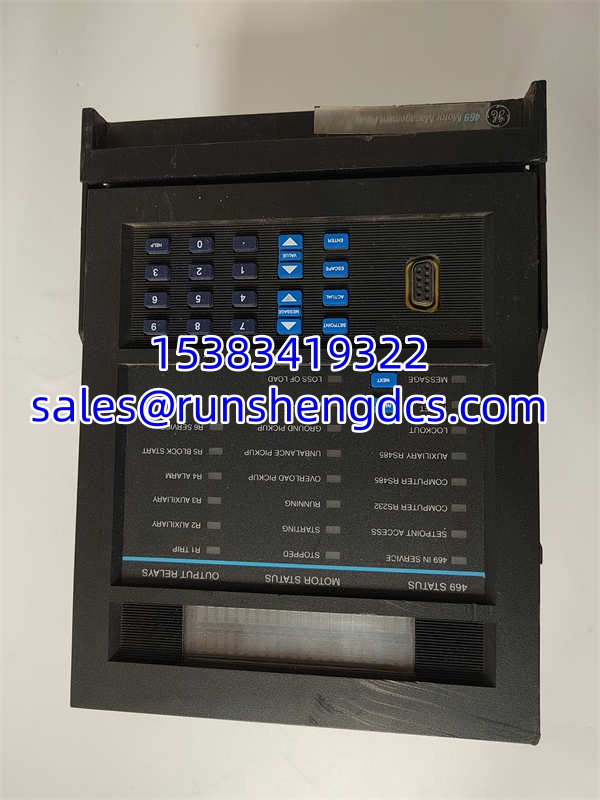
Photograph the nameplate. Record the full part number (SR469-P5-HI-A20), serial number, firmware revision, and date code. Cross-reference the firmware version against the target installation’s existing relay — mismatched firmware is the most common reason a replacement unit fails to communicate or trips on settings it should not. - Visual & Mechanical Inspection
Check the PCB for cold solder joints, capacitor bulging, or thermal stress marks. Inspect the rear terminal blocks for stripped screws or corroded contacts. Verify the panel-door cutout gasket is intact — a damaged seal compromises the IP rating in wet MCC environments. - Electrical Parameter Tests
Apply control power at both AC and DC extremes (e.g., 85 VAC and 265 VAC). Measure output relay contact resistance under load. Inject test currents into the CT inputs and verify that measured values on the front-panel display track within ±2% of injected values. Confirm 4–20 mA outputs scale correctly across the full range using a calibrated loop meter. - Functional Verification
If a test bench is available, simulate a thermal overload event and confirm the relay trips at the configured setpoint. Test RTD inputs with a decade resistance box. Verify Modbus RTU communication over RS-485 by polling the relay from a laptop running a terminal program. Log all results. - Final QC & Anti-Static Packaging
Label with QC pass status, test date, and firmware revision. Pack in anti-static shielding. Include a note that the replacement unit must be loaded with the site-specific settings file before commissioning — it will not operate correctly with factory defaults.
Field Engineer Gotchas
- Firmware Revision Will Haunt You
The SR469 family has gone through multiple firmware releases over its production life. A surplus unit with older firmware may not support setting parameters that your current configuration file references. The relay might boot up fine but reject the settings file during download. Always read the firmware version off the front panel or via the service port before assuming the unit is a drop-in replacement. - CT Ratio Must Match the Motor Nameplate
The relay calculates thermal capacity based on per-unit current. If the CT ratio programmed into the relay does not match the actual installed CTs, every protection function — thermal overload, stall, unbalance — will operate on wrong current values. This is not a “close enough” parameter. Verify the CT ratio against the motor nameplate FLA and the installed CT ratio before energizing. - The “A20” Analog Outputs Need Scaling Configuration
The 4–20 mA outputs do not auto-configure. Each output channel must be assigned a source variable (e.g., phase A current, thermal capacity used, kW) and scaled to the correct engineering units. A common mistake is installing the relay, seeing 4 mA on all outputs, and assuming they are broken. They are not broken — they are unconfigured. - RTD Wiring Polarity Matters on Pt100 Channels
The SR469 supports both 2-wire and 3-wire RTD configurations. If you wire a 3-wire Pt100 as a 2-wire, the lead resistance compensation will be wrong, and bearing temperature readings will drift high. Check the wiring diagram in the relay manual for the specific RTD type installed on the motor. - Do Not Ignore the Starts-Per-Hour Setting
The relay enforces a maximum starts-per-hour limit to protect the motor from repeated acceleration heating. If this is set too high (or disabled), the motor can be restarted repeatedly during a process upset without adequate cooling time between starts. This is a protection function, not a convenience setting.
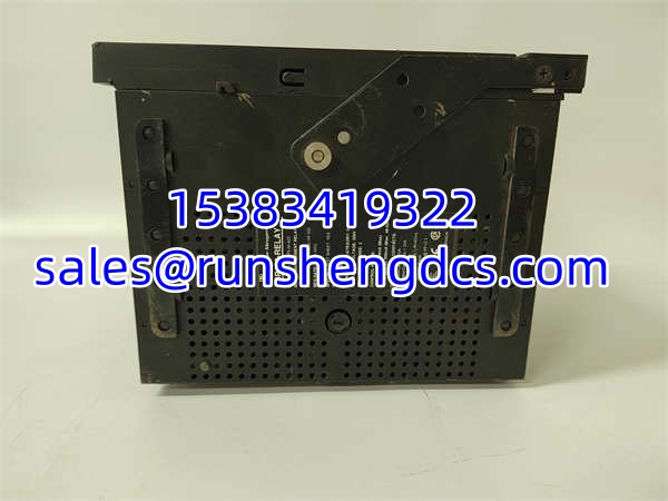
GE SR469-P5-HI-A20
Application Scenarios
- Medium-voltage motor protection in oil and gas production facilities — The SR469 protects large compressors, pumps, and fans where motor replacement costs run into hundreds of thousands of dollars and unplanned downtime is not an option.
- MCC bucket integration in power generation plants — Installed in motor control center buckets for boiler feed pumps, induced draft fans, and circulating water pumps, providing both protection and analog retransmission to the plant DCS.
- Mining and mineral processing — Protects conveyors, crushers, and grinding mills where stall and jam conditions are common and the relay’s start supervision and thermal memory functions prevent motor burnout.
- Water and wastewater treatment — Used on large raw water intake pumps and aeration blowers where phase unbalance from utility supply variations can damage motors over time.
FAQ
This relay has been marked as stop-production by multiple distributors. GE’s Multilin product line has evolved, and newer platforms exist. However, the remains widely deployed, and surplus/refurbished units are available through industrial spare-parts channels. Verify availability and lead time with your supplier before planning a project around it.
Can I use this relay on a low-voltage motor?
The is designed primarily for medium-voltage motors, but it can protect LV motors as well. The key requirement is that the phase CTs match the motor’s full-load current. The relay’s protection algorithms (thermal overload, stall, unbalance) work the same regardless of motor voltage class.
The “-E” suffix typically indicates an enhanced or revised hardware/firmware revision within the same product family. Functionally, it is the same relay platform. If your existing installation uses the “-E” variant, match it. If you are installing fresh, either variant will work — but keep firmware versions consistent across redundant or paired installations.
Does this relay support Ethernet communication?
The base -P5-HI-A20 communicates via RS-485 (Modbus RTU) and has a front-panel RS-232 service port. Ethernet is not a standard interface on this model. If your DCS requires Ethernet, you will need a protocol gateway or a newer relay platform that includes native Ethernet.
How do I load settings into a replacement unit?
Connect a laptop to the front RS-232 service port using GE Multilin’s configuration software (typically EnerVista or the 469 setup tool). Transfer the site-specific settings file from your backup. Do not attempt to manually re-enter all settings — the relay has hundreds of configurable parameters, and manual entry is error-prone.
What is the typical surplus market price?
Pricing varies significantly by condition, firmware revision, and supplier. Surplus units have been listed in the range of approximately US1,000–6,000 depending on the vendor and whether the unit is new-old-stock or refurbished. Get a quote with the serial number and firmware revision visible before committing.
No. A factory-default unit has no CT ratios, no motor nameplate data, no RTD configuration, and no protection setpoints loaded. It must be configured with your motor’s specific parameters before it provides meaningful protection. Installing an unconfigured relay and energizing the motor is a fast way to damage equipment.