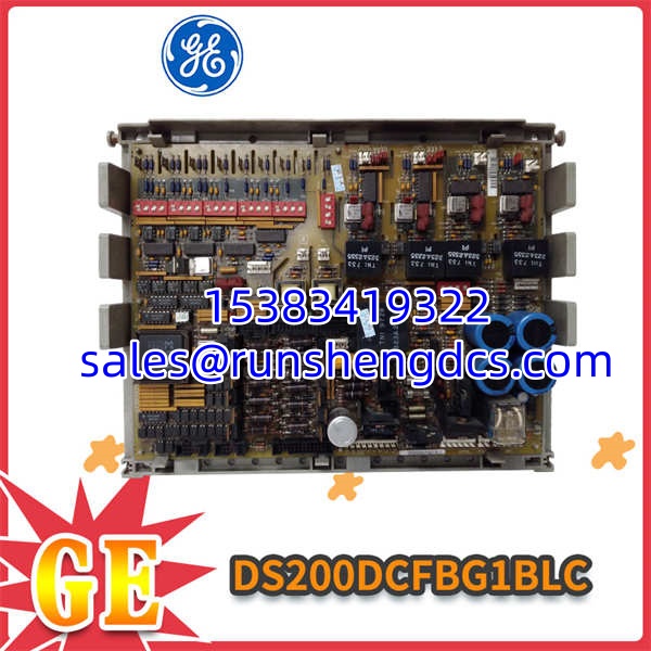

Description
Key Technical Specifications
| Parameter | Specification | Notes |
|---|---|---|
| Input Voltage | 38 to 115 VAC | Wide-range AC input |
| Input Frequency | 0 to 500 kHz | Varies with input voltage |
| User Config | 12 Jumpers, 7 DIP Switches | SW4 adjusts VCO output bridge |
| Status Indicators | 1 Neon, 2 LEDs | Neon = 115VAC fuse; LEDs = ±24VDC fuses |
| Circuit Protection | 3 Internal Fuses | Protects against surges/interruptions |
| Diagnostics | 5 Integrated Test Points | For live voltage level monitoring |
| Key IC Circuits | VCO, Attenuation, Zero-Cross | Motor voltage & contactor drive |
| Drive Compatibility | DC2K, AC2K, CB2K, ME2K, FC2K | Cross-compatible with multiple GE drives |
| System Role | Control & Excitation Power | Powers logic, not main motor bus |
Product Introduction
Turbine control systems running on legacy Mark V hardware face a brutal reality: when the control-level power supply dies, the entire turbine management system goes blind. The DS200DCFBG1BLC is the unsung workhorse inside the Speedtronic cabinet, converting raw 38-115 VAC line power into the clean, regulated DC voltages that the Mark V logic boards actually need to survive.
This board doesn’t just distribute power; it actively monitors its own health and the health of the AC line. With three protected fuses, dedicated neon/LED indicators for ±24VDC and 115VAC faults, and five test points for live troubleshooting, it gives maintenance teams a fighting chance during midnight outages. The 12 jumpers and 7 DIP switches allow field configuration for specific drive topologies, but that same flexibility is a trap for the unprepared. Bottom line — it’s a critical, irreplaceable link in a discontinued system, and finding a verified spare is getting harder every year.
QA/QC Transparency SOP
- Intake & Origin Verification: Visual inspection of the PCB for thermal damage, cracked solder joints around heavy components, and corrosion. We verify the exact “BLC” suffix revision, as earlier revisions may have different jumper layouts.
- Live Functional Testing: Board mounted on a Mark V test rack with 115 VAC applied. We verify all three fuse circuits are intact and measure regulated outputs against OEM spec before connecting any downstream logic.
- Electrical Parameter Tests: Continuity check on all 5 test points using a Fluke 87V. Megger test on AC input isolation to ensure no dielectric breakdown from years of thermal cycling.
- Firmware/Config Verification: Document all 12 jumper positions and 7 DIP switch settings. Photograph the board configuration before testing to ensure the buyer can replicate the exact setup in their cabinet.
- Final QC & Anti-Static Packaging: Functional test report with measured voltages attached. Board sealed in ESD shielding bag with desiccant; rigid foam corner protectors applied to prevent DIP switch damage during shipping.
Field Engineer Gotchas
- DIP Switch SW4 Misconfiguration: Risk: SW4 adjusts voltage to the VCO output bridge circuit. Wrong setting = erratic excitation or board failure. Fix: Document existing switch positions BEFORE pulling the board. War Story: Replaced a DS200DCFBG1BLC and didn’t check SW4. The turbine wouldn’t reach sync speed because the VCO was getting 2V too much. Spent 4 hours chasing a mechanical issue when it was a DIP switch.
- Fuse Indicator Misinterpretation: Risk: Assuming the neon light means “board is powered.” It actually means “115 VAC fuse is BLOWN.” Fix: Neon ON = problem. LEDs ON = ±24VDC fuses blown. Blunt Truth: Read the silkscreen. I’ve seen techs celebrate because the neon lit up, not realizing they just confirmed a dead fuse.
- Test Point Ground Loops: Risk: Probing the 5 test points with a grounded oscilloscope while the board is in-cabinet can create a ground path through your scope. Fix: Use isolated differential probes or verify your scope is floating. Warning: These boards run in high-noise environments. A bad ground reference will give you garbage readings and possibly fry your test equipment.
- Cross-Compatibility Assumptions: Risk: Assuming any DS200DCFBG1Bxx revision will drop in. Fix: The “LC” suffix matters. Earlier revisions may lack certain protection circuits or have different jumper assignments. Note: Verify with OEM documentation before installing a different suffix. “Close enough” in turbine control is how you get a trip.
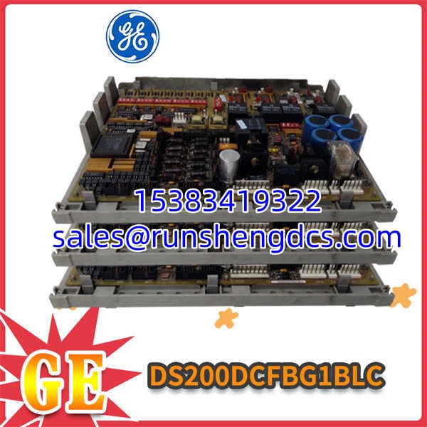
GE DS200DCFBG1BLC
Application Scenarios
- Gas Turbine Speedtronic Cabinets: Mark V control systems in power generation requiring reliable control-level power distribution and excitation supply for GE Frame 5/6/7 turbines.
- Industrial Drive Retrofits: DC2000 and AC2000 drive systems in manufacturing where the original power board has failed after 20+ years of thermal cycling.
- Wind Turbine Pitch/Yaw Control: Legacy GE wind turbine converters using Mark V-derived control hardware in unheated nacelle cabinets.
FAQ
Q: Can I substitute a DS200DCFBG1BLA for the BLC?
A: Not without verification. The suffix letter indicates hardware revision. Check the jumper layout, SW4 function, and fuse ratings against your OEM manual. Different revisions have caused field failures.
Q: What does the neon light actually indicate?
A: Neon ON means the 115 VAC line fuse is blown. Neon OFF means the fuse is good. The two LEDs indicate ±24VDC fuse status (LED ON = fuse blown). Confusing these is a common troubleshooting mistake.
Q: Is this board compatible with Mark VI systems?
A: No. This is strictly a Mark V / Speedtronic component. Mark VI uses a completely different power architecture. Don’t even try to force it.
Q: How do I verify the board is healthy before installing?
A: Check the 5 test points with a multimeter BEFORE connecting to the backplane. Verify AC input, then check regulated DC outputs. If the fuses are good but outputs are dead, the board has internal failure.
Q: Can I repair this board in-house?
A: Technically yes, practically no. The VCO and zero-cross circuits use custom GE ICs that aren’t commercially available. Unless you have a donor board for parts, component-level repair is a gamble.
Q: What drives accept this power board?
A: DC2000, AC2000, CB2000, ME2000, and FC2000 series. Verify your specific drive model against the OEM compatibility list. Not all variants use the same power configuration.
Q: Is this still available from GE?
A: Mark V is fully discontinued. GE no longer manufactures this board. Your only options are surplus stock, refurbished units, or third-party rebuilds. Secure spares now; the supply is finite.