
Description
Key Technical Specifications
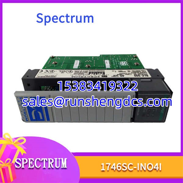
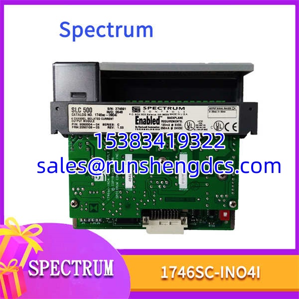
- Model Number: 1746SC-INO4I
- Manufacturer: Spectrum Controls
- Series: SLC 500 / PLC-5 Compatible
- Output Channels: 4 Isolated Current Outputs
- Resolution: 16-Bit
- Channel Isolation: 750 VDC (Channel-to-Channel, Channel-to-Backplane)
- Output Range: 0-20 mA, 4-20 mA (Programmable per Channel)
- Accuracy: ±0.08% of Full Scale @ 25°C
- Update Time: 33.7 ms (All 4 Channels)
- Power Supply: 24 VDC External or Backplane (DIP Selectable)
Functional Role & Application Analysis
The Spectrum 1746SC-INO4I is a direct-fit replacement for legacy Allen-Bradley analog output modules in SLC 500 and PLC-5 systems. It solves the critical problem of sourcing obsolete I/O without requiring a costly and risky control system migration. This module provides four independently programmable, galvanically isolated current outputs, eliminating the need for external signal isolators in noisy industrial environments. Its 750 VDC channel-to-channel isolation protects sensitive backplane electronics from ground loops and field transients, a common failure point in aging infrastructure.
Typical deployment scenarios include:
- Final Control Element Drive: Sending precise 4-20 mA signals to control valves, VFDs, or damper actuators from an SLC 500 processor.
- Noise Immunity in Harsh Environments: Deploying in panels with high EMI from motor drives or welders, where standard analog cards fail due to ground potential differences.
- Legacy System Maintenance: Replacing failed AB 1746-NO4I or similar modules with a modern, readily available equivalent that requires no ladder logic changes.
- Mixed Signal Applications: Using different output ranges on each channel (e.g., Ch0 at 4-20mA for a valve, Ch1 at 0-20mA for a display) within a single module slot.
Our Quality Standard & Testing Process
Analog output failures are insidious; a card can power on but still drive a valve to the wrong position. We test for functional accuracy, not just electrical continuity. Every 1746SC-INO4I is validated on a live SLC 500 rack to ensure it meets original performance specifications.
- Visual & Component Inspection: PCB is inspected for thermal damage, electrolytic capacitor leakage, and connector integrity. All solder joints are verified.
- Live System Test: Module is installed in a powered SLC 500 chassis. We verify backplane communication and correct slot recognition by the processor.
- Full-Range Accuracy Test: Using a precision current source and multimeter, we command 0%, 50%, and 100% output on all four channels. Each point is measured and must fall within the ±0.08% accuracy spec.
- Isolation Verification: We perform a hi-pot test to confirm the 750 VDC isolation barrier between channels and backplane is intact.
- Warranty Backing: Only units passing all electrical and functional tests are shipped with our 12-month warranty. We guarantee performance, not just power-on status.
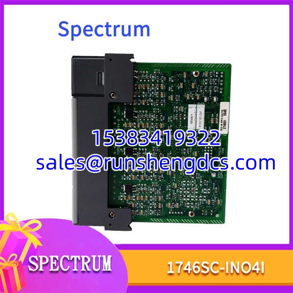
Spectrum-1746SC-INO4I
Compatibility & Migration Paths
This module is a functional replacement, not a universal plug-and-play part. Configuration and power setup must be verified to avoid installation failures. Do not assume compatibility based on form factor alone.
- Power Supply Selection: The module has a DIP switch for power source. You must set this to match your installation:
EXTfor external 24 VDC orRACKfor backplane power. Incorrect setting will prevent operation or damage the module. - Controller Compatibility: Confirmed compatible with SLC 5/03, 5/04, 5/05, and PLC-5 processors. Verify your CPU firmware revision supports third-party analog modules if using older firmware.
- Ladder Logic: No special SPIO CONFIG is required. The module auto-configures its I/O mapping. However, you must ensure your ladder logic writes to the correct output file addresses (O:e.0 to O:e.3 for data).
- Terminal Block: Uses a standard 1746-series 16-position terminal block. Verify your existing terminal block is not damaged or corroded before reusing.
- Get Expert Help: Send us a photo of your current module’s DIP switch settings and your CPU model. We will confirm the correct power configuration and provide the exact output file addressing for your slot before you order.