
Description
Key Technical Specifications
- Supply voltage: 24 VDC, operating range 22–35 VDC (+40% / −5%)
- Power consumption: <25 VA
- Primary command input: 0–9 V referenced to M0
- Differential command input: 0–10 V, 100 kΩ input impedance
- Max solenoid output current: 800 mA (+10% / −5%)
- Adjustable bias current: 10–300 mA via on‑board potentiometer
- Ramp time selection: 30 ms to 1 s or 30 ms to 5 s (jumper selectable)
- Output clock frequency: 100 Hz or 200 Hz, ±10% tolerance
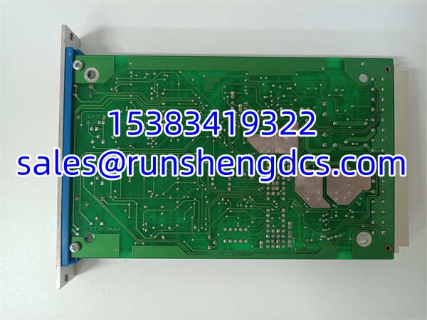
- Form factor: 3 HE / 3 TE Eurocard, 100 × 160 mm PCB
- Backplane connector: 32‑pin male DIN 41612 Form D
- Operating ambient temperature: 0 °C to +50 °C
- Built‑in protections: Reverse polarity, solenoid short‑circuit protection
- Typical MTBF: 212,000 hours at 40 °C ambient
Product Introduction
Many press and injection molding lines still run VT2000 hardware. A failed amplifier drops hydraulic pressure regulation immediately, forcing unplanned stops. No new factory builds ship, so maintenance teams hold tested spare cards to avoid full hydraulic retrofit downtime. This Eurocard plugs into compatible VT3002 card racks. It accepts analog setpoint signals from PLC or analog controllers, applies user‑defined ramps, then outputs a pulse‑width modulated current to the valve solenoid. No position feedback loop runs on this card. Typical current settle time sits under 22 ms for a full‑scale step change. Bottom line — it works, but all potentiometer settings must match the valve coil parameters before startup.
QA/QC Transparency SOP
- Intake & Origin Verification. Confirm printed model marking VT2000‑52. Inspect PCB for burnt traces, swollen electrolytic capacitors, corrosion on the DIN 41612 pins. Document front panel, component side and connector photos. Reject units with cracked solder joints or physical connector damage.
- Live Functional Testing (Comms, I/O, Load). Mount card in validated VT3002 rack with 24 VDC supply. Feed 0–10 V reference signal from a programmable signal generator. Drive a resistive load matching typical proportional valve coil impedance. Sweep command values across full range, verify output current tracks setpoint, test both ramp ranges and both clock frequency settings. Run continuous 4‑hour thermal soak with periodic setpoint steps.
- Electrical Parameter Tests (Megger, Continuity). De‑energize test rack. Apply 500 VDC megger between signal pins and chassis ground; pass threshold >100 MΩ. Check continuity on every DIN connector pin, confirm no unintended shorts between adjacent channels or supply lines with a Fluke 87V.
- Firmware/Config Verification. This design uses analog circuitry, no firmware. Record factory jumper positions for S1 (ramp range) and S2 (dither frequency). Log potentiometer baseline positions so customer can reset if needed. Flag cards with undocumented component modifications or cut traces.
- Final QC & Anti-Static Packaging. Clean DIN connector pins with isopropyl alcohol. Secure front‑panel adjustment knobs. Place unit inside ESD shielding bag with foam edge guards. Pack into rigid shock‑resistant carton. Attach unique test ID listing measured current linearity and ramp timing results.
Field Engineer Gotchas
- Jumper setting mismatch. Risk: S1 and S2 jumpers stored on old card may not match new replacement. Ramp times or dither frequency shift after swap, causing unstable pressure oscillation. Solution: Record jumper positions from the original card before removal. One maintenance tech swapped a VT2000‑52 without checking jumpers; machine overshot set pressure and tripped the high‑pressure interlock within 10 seconds.
- Solenoid coil resistance mismatch. Risk: Driving a coil outside 19.5–30 Ω range causes overcurrent shutdown or weak valve response, even if amplifier tests fine on a bench resistor load. Solution: Measure coil cold resistance before commissioning. Bench tests do not replicate real coil thermal drift.
- No hot‑swap support. Risk: Pulling the live card from the rack cuts solenoid drive instantly. Uncontrolled pressure drop can damage tooling or workpieces. Solution: Lock out hydraulic supply and bypass control loops before powering down the rack.
- ESD vulnerability. Risk: Exposed analog op‑amp inputs can be damaged by static discharge during handling. Damage may not appear until thermal cycling weeks later. Solution: Wear grounded wrist strap at all times while handling the board.
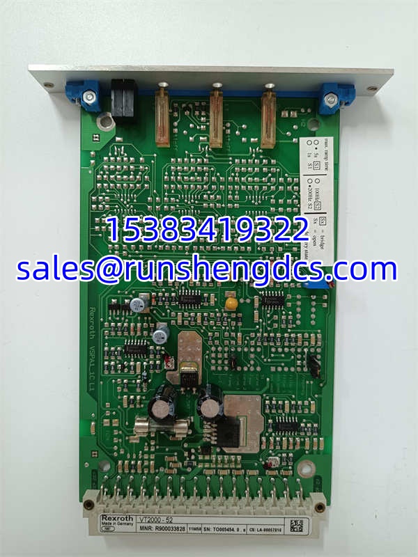
REXROTH VT2000-52
Application Scenarios
Plastic injection molding machines use VT2000‑52 to regulate mold clamping pressure via proportional pressure valves with no LVDT feedback. Hydraulic metal stamping presses deploy these amplifiers to control blank‑holder pressure during draw operations. Paper mill hydraulic tension control racks rely on VT2000‑52 for slow, ramped pressure adjustments to avoid web breaks. Heavy‑duty test benches for hydraulic component qualification use multiple VT2000‑52 cards for independent pressure channel control.
Case study: A 1,200‑ton stamping press had slow, drifting clamping pressure. Technicians first replaced the proportional valve. Bench testing of the old amplifier found drift in the bias current potentiometer. Installing a tested ‑52 restored stable pressure within specification; no hydraulic piping changes required.
FAQ
Q: Can ‑52 be hot‑swapped in the card rack? A: No. Removing a powered card immediately cuts solenoid drive. Hydraulic pressure will drop with no controlled ramp. Full rack shutdown is required.
Q: Can this amplifier drive proportional valves with position feedback? A: No. ‑52 has no feedback input or closed‑loop position regulation. Use a different Rexroth amplifier series for LVDT‑equipped valves.
Q: What rack does ‑52 require? A: It fits VT3002‑2X/32 card holders. The rack does not supply power by itself; a separate VT‑NE30‑1X power unit provides the 24 VDC rail.
Q: What lead time applies for tested surplus stock? A: Pre‑tested units ship 2–5 business days. Units needing capacitor replacement and full thermal soak testing take 10–14 days. No new OEM production exists.
Q: Can I swap a ‑4X directly with a ‑52? A: Pinout is compatible, but default jumper settings differ. Verify ramp and dither jumpers after swap, then re‑tune zero, bias and gain. Direct swap without tuning often creates instability.
Q: Why does bench testing pass but the machine still oscillates? A: Bench resistive loads do not replicate valve inductance and hydraulic spring dynamics. Oscillation usually comes from incorrect ramp time or dither frequency, not the amplifier itself. Tune on the actual machine.
Q: What measurement signals come out of the front panel test ports? A: W port outputs 0–6 V proportional to command value; I port outputs 0–800 mV proportional to actual solenoid current. You can use these for troubleshooting without disconnecting the valve.