
Description
Key Technical Specifications
| Parameter | Specification |
|---|---|
| Product Type | UCSB Controller Module |
| System Platform | Mark VIe / EX2100e / LS2100e |
| Processor | Intel EP80579, 600 MHz |
| Memory | 256 MB DDR2 SDRAM with ECC + 2 GB NAND flash |
| Operating System | QNX Neutrino real-time OS |
| IONet Ports | 3 × Ethernet (R/S/T redundant IONet) |
| ENET Ports | 3 × Ethernet (HNMI, peer-to-peer, historian connections) |
| USB Port | 1 × USB (front panel) |
| Time Sync | IEEE 1588 PTP, within 100 μs across R/S/T networks |
| Power Supply | 18–30 VDC (nominal 24/28 VDC), max 1.5 A |
| Operating Temperature | -40°C to +85°C (-22°F to 149°F) |
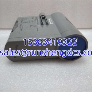
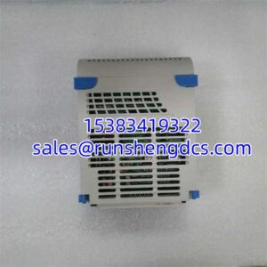
| Cooling | Fanless, convection-cooled (heatsink fins) |
| Battery | None (flash-based, no battery backup required) |
| Jumpers | None (jumper-free configuration) |
| Form Factor | Single-module, panel-mount (direct to metal backplate) |
| Weight | ~2.4 lbs (~1.1 kg) |
| Dimensions | ~150 mm × 100 mm × 50 mm |
| HazLoc Certifications | UL E207685 (Class I, Div 2, Groups A–D); ATEX Zone 2, IIC (UL DEMKO 12 ATEX 1114875X) |
| Country of Origin | USA |
| Warranty | 12 months (supplier-dependent) |
| HS Code | 8471.41 (Automatic data processing machines) |
Product Introduction
The IS420UCSBH1A is GE’s first-generation UCSB (Universal Control Safety Bus) controller, forming the computational core of the Mark VIe control safety system. Unlike the older UCV controllers that sat in VME racks and hosted I/O directly on the backplane, the UCSB architecture takes a fundamentally different approach: the controller is a standalone computer with no onboard I/O. Instead, it connects to remote I/O packs via three redundant IONet networks (R, S, and T), which are private Ethernet links dedicated to controller-to-I/O communication.
This architectural shift matters for reliability. Because every I/O network connects to every controller in the system, all controllers receive all input data simultaneously. If one controller is taken offline for maintenance, firmware update, or replacement, the remaining controllers continue to receive full I/O data — there is no single-point input loss. This is critical in turbine control, where losing a temperature or pressure reading during a controller swap could trigger an unnecessary trip.
The IS420UCSBH1A is powered by a 600 MHz Intel EP80579 processor with 256 MB of ECC-protected DDR2 SDRAM and 2 GB of NAND flash for program and configuration storage. It runs GE’s proprietary control software on the QNX Neutrino real-time operating system, capable of executing ladder logic or function block programs. Minor software changes can be made online without rebooting the controller — a significant operational advantage during commissioning or troubleshooting.
Time synchronization is handled via the IEEE 1588 Precision Time Protocol, which synchronizes all I/O packs and controllers across the R/S/T networks to within 100 microseconds. This level of precision is essential for coordinated control in multi-controller systems, including dual-redundant and triple-modular-redundant (TMR) configurations. In TMR systems, the three controllers exchange voting and synchronization data over the IONets to achieve fault-tolerant operation.
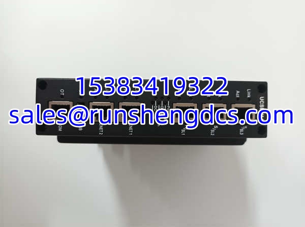
The front panel features six Ethernet ports total: three dedicated to the R/S/T IONet networks and three additional ENET ports for connecting HNMIs (Human-Machine Interfaces), other controllers, historians, and peer-to-peer data exchange. A single USB port provides local connectivity for configuration via GE’s ToolboxST application.
Physically, the module is designed for harsh industrial environments. It is fanless (convection-cooled via heatsink fins), battery-free (all data stored in flash), and jumper-free. It mounts directly to a metal panel backplate with vertical airflow clearance for passive cooling. The operating temperature range of -40°C to +85°C and ATEX Zone 2 / Class I Div 2 certifications make it suitable for installation in hazardous areas such as gas compressor stations and turbine enclosures.
Why does this matter for TCO? The UCSB architecture eliminates the VME backplane — one less point of failure. The fanless, battery-free design eliminates two common wear-out mechanisms. The redundant IONet topology ensures that controller maintenance does not compromise I/O visibility. And the IEEE 1588 sync ensures that in TMR configurations, all three controllers are making decisions based on time-aligned data. For plants running GE turbine control systems, the IS420UCSBH1A is the brain that keeps the turbine spinning safely.
QA/QC Transparency SOP
Every IS420UCSBH1A we ship goes through a five-step verification process.
- Intake & Origin Verification: We trace each unit’s serial number and part number back to GE’s manufacturing records. We verify PCB silk-screen fonts, component date codes, and processor markings against known GE standards. The IS420UCSBH1A must have an Intel EP80579 processor (not the MPC7534 variant used in some other UCSB models) and 256 MB ECC SDRAM. Any unit with mismatched date codes or incorrect processor markings is rejected.
- Visual & Mechanical Inspection: We inspect the module for proper component seating, secure soldering, and absence of corrosion. We verify that all six Ethernet ports and the USB port are intact and undamaged. We check the heatsink fins for damage that could impair passive cooling. Any unit with mechanical defects is rejected.
- Functional Testing: We power up the controller with a 24/28 VDC supply and verify that it boots correctly into QNX Neutrino. We verify processor recognition, memory configuration (256 MB ECC SDRAM + 2 GB NAND flash), and that all six Ethernet ports link up correctly. We run the built-in diagnostics to verify flash integrity and USB functionality. Any unit with failed diagnostics or non-functional ports is rejected.
- IONet Communication Test: We connect the controller to a test IONet network and verify that it can communicate with I/O packs, exchange data, and synchronize clocks via IEEE 1588 protocol within the 100-microsecond specification. We verify redundancy by simulating a network failure on one IONet and confirming that the controller continues to receive I/O data via the remaining networks. Any unit with IONet communication failures is rejected.
- Final QC & Anti-Static Packaging: After passing all tests, each module is wrapped in Mil-Spec ESD shielding bags with desiccant packs and placed in double-walled corrugated boxes with foam corner protectors. A signed QC certificate with test data (including processor verification, memory test results, port functionality checks, and IONet communication test results) is included in every shipment.
Field Engineer Gotchas
IONet Topology — R/S/T Must Be Physically Separate
The three IONet ports (R, S, T) must connect to three physically separate Ethernet networks. Do not connect all three ports to the same switch or the same VLAN — this defeats the redundancy purpose. Each IONet should have its own dedicated switch, its own cabling, and its own I/O pack connections. If two IONets share a common switch and that switch fails, you lose two-thirds of your I/O redundancy.
IEEE 1588 Sync — Verify Clock Alignment During Commissioning
After installing the IS420UCSBH1A, use ToolboxST to verify that the IEEE 1588 clock synchronization is within specification (100 microseconds) across all three IONets. If the sync drifts beyond this threshold, the controller may flag a synchronization fault and, in TMR configurations, could trigger a mismatch trip. Check the sync status LEDs on the front panel — they should indicate locked/synchronized status.
Fanless Cooling — Ensure Vertical Airflow Clearance
The is convection-cooled via heatsink fins — it has no fan. When mounting the module to a panel, ensure that there is adequate vertical clearance above and below the module for natural convection airflow. Do not mount the module horizontally or in an enclosed space without ventilation. Overheating due to restricted airflow can cause the processor to throttle or shut down, resulting in a controller fault.
Power Supply — Verify 18–30 VDC Range
The operates on 18–30 VDC (nominal 24/28 VDC) with a maximum current draw of 1.5 A. Verify that your power supply can deliver sufficient current, especially during startup when the controller draws peak current. An undersized power supply can cause voltage sag during boot, preventing the controller from starting. Measure the voltage at the controller’s power terminals during startup to ensure it stays above 18 VDC.
Flash-Based Storage — No Battery, But Watch Flash Wear
The uses NAND flash for program and configuration storage — there is no battery. This is an advantage (no battery replacement needed), but flash memory has a finite write endurance. Avoid excessive online configuration changes or frequent firmware updates, as each write cycle consumes flash endurance. GE’s software manages this automatically under normal operation, but excessive manual writes can accelerate flash wear.
ToolboxST Configuration — Use the Correct Controller Type
When configuring the in ToolboxST, ensure you select the correct controller type (UCSB, not UCSC or UCV). The uses different hardware and firmware than the UCSC controller, even though the software interface is similar. Selecting the wrong controller type can result in configuration download failures or unexpected behavior.
ATEX / HazLoc Installation — Follow Certification Requirements
If installing the in a hazardous area (ATEX Zone 2 or Class I, Div 2), ensure that the installation complies with the certification requirements (UL DEMKO 12 ATEX 1114875X for ATEX; UL E207685 for Class I, Div 2). This includes using certified cable glands, proper grounding, and ensuring that the module is mounted in a certified enclosure if required. Non-compliant installation can void the certification and create a safety hazard.
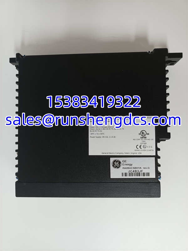
GE IS420UCSBH1A
Application Scenarios
Gas Turbine Primary Control in Combined-Cycle Power Plants
The serves as the primary controller for GE Frame 7FA, 9FA, and LM series gas turbines in combined-cycle power plants. It executes real-time control algorithms for fuel scheduling, speed control, exhaust temperature management, and startup/shutdown sequencing. The triple IONet redundancy ensures that I/O data is never lost, even during controller maintenance. The IEEE 1588 sync ensures precise coordination with other controllers in the system.
Steam Turbine Control in Cogeneration Facilities
Industrial cogeneration facilities use the to control extraction and condensing steam turbines. The controller manages extraction pressure control, load sharing, and emergency trip logic. The fanless, battery-free design is ideal for steam turbine environments where high ambient temperatures and vibration would degrade fan-cooled or battery-backed controllers. The -40°C to +85°C operating range handles the temperature variations found in turbine halls.
Excitation System Control (EX2100e Platform)
The is certified for use in GE’s EX2100e excitation system, where it controls the generator field excitation to maintain terminal voltage and reactive power output. The high-speed IONet communication ensures rapid response to voltage transients, and the redundant architecture provides fault tolerance for this critical function. The ATEX Zone 2 certification allows installation in generator enclosures where explosive gas atmospheres may be present.
Servo Drive Control (LS2100e Platform)
In GE’s LS2100e servo drive system, the controls variable-frequency drives that regulate motor speed and torque in industrial processes. The real-time QNX OS and 600 MHz processor provide the computational headroom needed for complex vector control algorithms. The triple IONet redundancy ensures that drive control signals are never interrupted.
Case Study: UCSB Controller Redundancy Prevents Turbine Trip During Firmware Update
A combined-cycle power plant in Texas needed to update the firmware on their Mark VIe gas turbine controllers. In the older Mark VI system with UCV controllers, a firmware update required taking the controller offline, which meant running on a single controller with no redundancy — a risky proposition during baseload operation. With the ‘s UCSB architecture, the plant was able to update one controller at a time while the other two controllers (in TMR configuration) continued to receive full I/O data via the R/S/T IONets. The update was performed online without any interruption to turbine operation. The total downtime was zero, and the plant avoided an estimated $200,000 in lost generation that would have been incurred if a scheduled outage had been required.
FAQ
A: The uses a 600 MHz Intel EP80579 processor, while the IS420UCSBH4A uses a faster 1066 MHz Intel EP80579 processor. Both are UCSB controllers in the Mark VIe family with the same IONet architecture and software interface, but the H4A variant provides more processing headroom for complex control strategies.
A: The is similar to the UCSC controller in terms of software interface and functionality, but the hardware is different. They are not direct drop-in replacements — the backplane, power supply, and I/O network topology may differ. Consult GE documentation or a qualified GE service engineer before attempting a replacement.
Q: What is IONet and how is it different from regular Ethernet?
A: IONet is GE’s proprietary dedicated Ethernet network that connects UCSB controllers to remote I/O packs. Unlike regular Ethernet, which can carry any type of traffic, IONet only supports communication between Mark VIe I/O modules and controllers. This dedicated topology ensures deterministic, low-latency communication for real-time control. The three redundant IONets (R, S, T) provide fault tolerance — if one network fails, the controller continues to receive I/O data via the remaining networks.
A: No. The is battery-free. All program and configuration data is stored in 2 GB of NAND flash memory. This eliminates the need for periodic battery replacement, which is a common maintenance task on older controllers.
Q: What is the operating temperature range?
A: The operates from -40°C to +85°C (-22°F to 149°F), making it suitable for harsh industrial environments including outdoor installations and unconditioned control rooms.
Q: Can I make changes to the control logic while the controller is running?
A: Yes. The supports online modification of control logic. Minor changes to ladder logic or function block programs can be made and downloaded without rebooting the controller or interrupting turbine operation. This is a significant advantage during commissioning and troubleshooting.
A: The is certified for Class I, Division 2, Groups A, B, C, D (UL E207685) and ATEX Zone 2, Group IIC (UL DEMKO 12 ATEX 1114875X). This allows installation in hazardous areas where explosive gas atmospheres may be present under abnormal conditions.
A: Configuration is done using GE’s ToolboxST application, which connects to the controller via one of the ENET ports or the USB port. ToolboxST allows you to download control logic, configure I/O mappings, set network parameters, and monitor controller status.