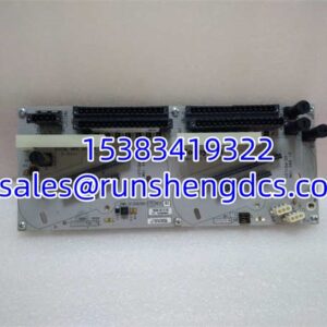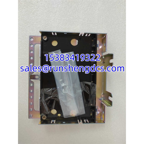

Description
Key Technical Specifications
| Parameter | Specification |
|---|---|
| Part Number | IS230SNRTH2A |
| Manufacturer | GE Energy / GE Vernova |
| Product Type | RTD Input Terminal Board (T-Type) |
| System Platform | GE Speedtronic Mark VIe |
| Redundancy Architecture | TMR (Triple Modular Redundant) — 3 independent channels |
| Input Type | RTD (Resistance Temperature Detector), typically 3-wire |
| Supported Sensors | Pt100 / Pt1000 (verify against site configuration) |
| Connector Type | P5-style connector to I/O pack; screw-terminal or pluggable field terminals |
| Compatible I/O Packs | Mark VIe T-Type analog input packs (e.g., IS230T series — confirm per site BOM) |
| Operating Temperature | Typically 0°C to 60°C ambient (verify with OEM datasheet for exact range) |
| Mounting | DIN-rail or panel-mount within Mark VIe I/O cabinet |
| Standards Compliance | IEC 61131-2 (industrial control equipment); verify revision-specific certifications |
Product Introduction
Temperature measurement is the single most critical analog input on a gas turbine — exhaust gas temperature spread can be the earliest indicator of a combustion problem or a failing nozzle. The IS230SNRTH2A sits at the front end of that measurement chain, converting raw RTD resistance from the turbine casing and exhaust duct into conditioned signals that the Mark VIe I/O packs can digitize.
What makes this board worth specifying over a simplex alternative is the TMR architecture. Three independent RTD channels feed three separate I/O packs, and the Mark VIe controller performs a 2-out-of-3 vote on every scan. One failed RTD or one open wire does not trip the unit — the controller masks the bad channel and keeps running. That is the difference between a nuisance alarm at 2 a.m. and an unscheduled outage. For any turbine where availability matters, TMR RTD input is non-negotiable.
QA/QC Transparency SOP
- Intake & Origin Verification — Verify the full part number including any trailing revision suffix (e.g., G01, G02). Check for physical damage: cracked terminal blocks, corroded P5 connector pins, or burnt traces near the input protection circuitry.
- Live Functional Testing — Install the board in a Mark VIe test rack with a compatible T-Type I/O pack. Inject known resistance values (100 Ω, 150 Ω, 200 Ω) using a precision decade box or Fluke 5522A calibrator. Verify all three TMR channels read within tolerance.
- Electrical Parameter Tests — Megger test field terminals for insulation resistance (>100 MΩ at 250V DC). Continuity check on all three RTD input paths per channel. Verify no shorts between adjacent terminals.
- Firmware/Config Verification — While the terminal board itself is passive, confirm the mated I/O pack firmware revision matches the site baseline. A mismatched I/O pack firmware can cause scaling errors on the RTD readings.
- Final QC & Anti-Static Packaging — Label with test date, channel accuracy results, and technician ID. Protect the P5 connector with a dust cap. Ship in ESD bag with foam support to prevent terminal block damage.
Field Engineer Gotchas
- RTD Wire Configuration Mismatch — The board expects 3-wire RTDs. If someone wires a 2-wire RTD, the lead resistance gets added to the measurement and you will see a consistent positive temperature offset (often 5–10°C). Solution: Always verify the sensor type matches the configuration in ControlST. If you must use 2-wire, short the compensation lead at the terminal — but update the scaling factor.
- TMR Channel Imbalance — If one of the three RTD channels reads significantly different from the other two, the controller may flag a “sensor disagree” alarm. This is often a bad crimp or corroded terminal, not a failed board. War story: Spent three hours chasing a “failed RTD board” on a Frame 7FA only to find one of the three field wires had corroded at the junction box 40 meters away.
- P5 Connector Pin Damage — The P5 connector that mates with the I/O pack has fine-pitch pins. Forcing the connector or misaligning during installation can bend pins. Once bent, the channel is dead. Always use the guide rails and never force the connection.
- Ground Loop Noise — RTD circuits are low-level resistance measurements. Running RTD cables in the same tray as VFD output cables will inject noise and cause erratic readings. Solution: Use shielded, twisted-pair cable for RTD runs and ground the shield at one end only.
- Revision Suffix Trap — IS230SNRTH2A may ship with different trailing suffixes (e.g., G01 vs G02). These can have different terminal block layouts or protection circuitry. Always compare the physical board against the site’s existing installed board before swapping.
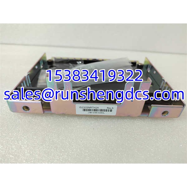
GE IS230SNRTH2A
Application Scenarios
- Gas turbine exhaust temperature monitoring — A Frame 9E uses 40+ RTDs around the exhaust diffuser. Each RTD feeds a TMR channel on the IS230SNRTH2A. A single open RTD does not trip the unit thanks to 2oo3 voting, but the alarm still prompts investigation.
- Steam turbine bearing temperature protection — Journal bearing pad temperatures are critical trip inputs. TMR RTD inputs ensure that a single failed sensor does not cause a false trip during startup, when bearing temperatures are changing rapidly.
- Generator stator winding temperature — RTDs embedded in the stator windings feed the Mark VIe via this terminal board. Accurate temperature measurement prevents insulation damage and extends generator life.
FAQ
Q: Is IS230SNRTH2A compatible with Mark VI (non-e) systems?
A: No. The is a Mark VIe T-Type terminal board. Mark VI uses a different I/O architecture (TCQA/TBQA boards in a VME core). The two platforms are not interchangeable.
Q: What RTD types does this board support?
A: Typically Pt100 (100 Ω at 0°C) and Pt1000, 3-wire configuration. The exact supported types depend on the mated I/O pack firmware and the ControlST configuration. Verify against your site’s I/O map.
Q: Can I use this board with a simplex I/O pack?
A: No. The is designed for TMR applications. Using it with a simplex I/O pack will leave two of the three channels unconnected. For simplex RTD inputs, GE offers S-Type terminal boards (e.g., IS230STAIH series).
Q: Does this board require calibration?
A: The terminal board itself is passive — it routes the RTD signal to the I/O pack. Calibration is performed at the I/O pack level using ControlST software. However, you should verify channel accuracy during commissioning using a precision resistance source.
A: The “T” in SNRTH denotes TMR (Triple Modular Redundant). The “L” in SNRLH typically denotes a different input type or simplex configuration. They are not interchangeable. Always match the board type to your system’s redundancy architecture.
Q: Is this part still available from GE?
A: The Mark VIe platform is still supported by GE Vernova, but availability of specific board revisions varies. Many users source from surplus or authorized distributors. Always verify the revision suffix matches your installed base.
Q: Can I substitute a different revision (e.g., G01 vs G02)?
A: Often yes, but not always. Revision changes can affect terminal block layout, protection components, or connector pinout. Compare the physical board and the GE drawing before installing a different revision. When in doubt, stick with the exact suffix on your existing board.