
Description
Key Technical Specifications
| Parameter | Specification |
|---|---|
| Manufacturer | GE (General Electric) |
| Model | IS230SNIDH1A |
| Product Type | Isolated Digital DIN-Rail I/O Module (SNI Pack) |
| System Platform | GE Speedtronic Mark VIe IS230 Series Turbine Control System |
| Input Channels | 8 isolated digital inputs |
| Output Channels | 8 isolated digital outputs |
| Operating Voltage | 24VDC |
| Response Time | <1 ms |
| Isolation | Galvanic isolation between field circuits and controller backplane |
| Mounting | Standard DIN-rail (35mm) |
| Operating Temperature | -40°C to +85°C |
| Dimensions | 100 mm × 70 mm × 35 mm |
| Housing Color | Green (standard GE Mark VIe SNI pack color) |
| Country of Origin | USA |
| Product Status | Legacy/discontinued (no longer in production by GE) |
| Warranty (distributor) | Typically 12 months from acceptance (varies by supplier) |
Product Introduction
The GE IS230SNIDH1A is an 8-channel isolated digital input and 8-channel isolated digital output DIN-rail module for GE’s Speedtronic Mark VIe gas and steam turbine control system. It belongs to the IS230 SNI (Simple Network I/O) family — GE’s distributed I/O architecture that allows I/O packs to be mounted on DIN rails near field devices, rather than being confined to the main Mark VIe VME rack. This distributed architecture reduces field wiring runs, simplifies panel layout, and improves signal integrity by keeping low-level digital signals close to their source.
At its core, the IS230SNIDH1A provides galvanic isolation between the Mark VIe controller and field devices. This isolation is critical in power generation environments, where ground potential differences between the turbine deck and the control room can create ground loops, and where switching transients from solenoid valves, relay coils, and motor starters can couple back into the control system and cause nuisance trips or even permanent damage to the controller’s I/O circuitry. The IS230SNIDH1A’s isolation barrier absorbs these transients and breaks ground loops, ensuring that only clean, validated digital signals reach the Mark VIe processor.
The module provides 8 isolated digital input channels and 8 isolated digital output channels, all operating at 24VDC — the standard control voltage in most power plants and industrial facilities. The input channels accept dry-contact closures, 24VDC discrete signals from proximity switches, limit switches, pressure switches, temperature switches, and other field devices. The output channels drive 24VDC loads such as relay coils, solenoid valves, indicator lamps, and alarm horns. Each channel is individually isolated, meaning a fault on one channel (e.g., a shorted solenoid) will not affect the other channels or the controller.
With a response time of less than 1 millisecond, the IS230SNIDH1A is fast enough for most turbine auxiliary control applications, including trip circuit monitoring, lube oil pressure switch status, hydraulic power unit valve control, turning gear interlocks, and fire protection system status monitoring. The module connects to the Mark VIe SNI network via a standard Ethernet-based fieldbus interface (typically EtherNet/IP or GE’s proprietary SNI protocol over Ethernet), allowing it to be daisy-chained with other SNI packs and located up to several hundred meters from the main controller rack.
The IS230SNIDH1A is housed in a compact green DIN-rail enclosure measuring 100 mm × 70 mm × 35 mm, designed to mount on standard 35mm DIN rail inside auxiliary junction boxes, marshalling cabinets, or directly on the turbine skid. Its wide operating temperature range of -40°C to +85°C makes it suitable for outdoor installations and unheated enclosures, which is common in combined-cycle plants where auxiliary equipment is located in remote areas of the facility.
As with all Mark VIe components, the is a legacy product that is no longer in production by GE. It is available through authorized surplus distributors and industrial automation spare parts suppliers, typically as new old stock (NOS) or factory-refurbished units. When sourcing replacements, always verify the module’s firmware version and ensure it is compatible with your Mark VIe system’s SNI network configuration.
QA/QC Transparency SOP
- Intake & Visual Inspection: Each module is inspected for physical damage — cracked or warped DIN-rail housing, broken terminal block connectors, burnt or discolored components (especially around the isolation barrier and output driver sections), corroded Ethernet communication port, or signs of moisture ingress (white residue on PCB). Units with charred components, swollen capacitors, or damaged terminal blocks are rejected.
- Isolation Barrier Integrity Test: Using a high-potential (hipot) tester, we verify the galvanic isolation between the field-side terminals and the communication-side circuitry. The isolation barrier must withstand the manufacturer’s specified test voltage (typically 1500VAC or 2500VDC for 1 minute) without breakdown. Any module that fails the hipot test is rejected, as a compromised isolation barrier defeats the module’s primary safety function.
- Digital Input Channel Verification: Each of the 8 input channels is tested by applying a 24VDC signal to the terminal and verifying that the module correctly registers the input state (ON/OFF) on the SNI network. We test both rising-edge and falling-edge transitions to confirm the <1ms response time specification. Channels that fail to register or show intermittent behavior are grounds for rejection.
- Digital Output Channel Verification: Each of the 8 output channels is tested by commanding the output ON and OFF via the SNI network and measuring the voltage at the output terminal with a multimeter. We verify that the output switches cleanly to 24VDC (ON) and 0VDC (OFF), and we measure the output current capability to ensure it meets the module’s rated load capacity. We also test for output short-circuit protection by briefly shorting the output and verifying that the module recovers without damage.
- SNI Network Communication Test: The module is connected to a Mark VIe SNI test network via its Ethernet port. We verify that the module is recognized by the SNI master, can be addressed correctly, and reports accurate I/O status to the controller. We test communication reliability over an extended period (minimum 24 hours) to detect any intermittent communication drops or data corruption.
- Temperature Stress Test (sample basis): For each batch of modules, a sample unit is placed in a temperature chamber and cycled between -40°C and +85°C for 10 cycles while operating. After the temperature cycling, the module is retested for input/output functionality and communication integrity. Any module that fails post-cycling tests results in rejection of the entire batch.
- Final QC & Anti-Static Packaging: After passing all tests, the module is placed in an anti-static bag with desiccant and shipped in a rigid box with foam inserts to protect the DIN-rail mounting clips and terminal block connectors. A test report with channel-by-channel verification is included.
Field Engineer Gotchas
- SNI network addressing and node ID configuration: The must be assigned a unique node ID on the Mark VIe SNI network. If two modules share the same node ID, they will conflict and cause communication failures. Always verify the node ID configuration in the Mark VIe ToolboxST software before commissioning. The node ID is typically set via DIP switches on the module or through software configuration — consult the specific hardware manual for your revision.
- Isolation voltage rating vs. field voltage: The provides galvanic isolation, but the isolation voltage rating has limits. Do not exceed the module’s rated field-side voltage (24VDC). Connecting higher-voltage signals (e.g., 110VDC or 125VDC trip circuits) directly to the inputs will damage the isolation barrier and potentially the module. For higher-voltage applications, use an intermediate relay to step down the voltage to 24VDC before connecting to the module.
- Output load current limits: Each output channel has a maximum current rating (typically 0.5A to 2A per channel, depending on the specific revision). If you are driving high-current loads such as large solenoid valves or multiple relay coils from a single output, use an external interposing relay. Exceeding the output current rating can cause the output driver to overheat and fail, potentially taking out adjacent channels.
- DIN-rail grounding and shield termination: The ‘s DIN-rail mounting clip provides a mechanical ground connection, but for optimal EMI performance, ensure the DIN rail itself is properly bonded to the cabinet ground. Shielded field wiring should have the shield terminated at one end only (typically at the module end) to avoid ground loops. Improper grounding can negate the benefits of the module’s galvanic isolation.
- SNI network cable length and topology: The SNI network uses standard Ethernet cabling (Cat5e or better), but the maximum cable length between nodes is limited (typically 100 meters per segment for copper Ethernet). If your SNI network spans longer distances, use fiber-optic media converters or Ethernet switches with fiber uplinks. Also, ensure the SNI network topology matches the configuration in the Mark VIe software — daisy-chain, star, or ring topologies must be correctly defined.
- Firmware version compatibility: The firmware must be compatible with the Mark VIe controller’s firmware version. A firmware mismatch can cause communication errors or incorrect I/O behavior. Before replacing a module, check the firmware version of the existing module (visible in ToolboxST) and ensure the replacement module has the same or a compatible firmware version. Firmware upgrades can be performed via the SNI network if needed.
- Response time considerations for trip circuits: While the has a <1ms response time, the total trip circuit response time includes the SNI network scan time, the Mark VIe controller scan time, and the output driver response time. For critical trip functions (e.g., overspeed trip, lube oil pressure low trip), verify that the total response time meets your safety system requirements. In some cases, hardwired trip circuits (bypassing the SNI network) may be required for the fastest possible response.
- Replacement for older Mark VI VME I/O: The is a Mark VIe SNI module and is not directly compatible with the older Mark VI VME I/O architecture. If you are upgrading from Mark VI to Mark VIe, you cannot simply swap IS200-series VME I/O cards for IS230 SNI packs — the entire I/O architecture, backplane, and network topology are different. Plan your upgrade carefully and consult the GE Mark VIe migration guide.
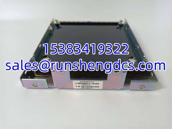
GE IS230SNIDH1A
Application Scenarios
- Gas turbine auxiliary system monitoring: In a 150 MW simple-cycle gas turbine installation, the is mounted on a DIN rail inside the turbine auxiliary cabinet. The 8 digital inputs monitor the status of critical auxiliary devices: lube oil pressure low switch, hydraulic power unit pressure switch, fuel gas supply pressure switch, compressor discharge pressure switch, turbine exhaust temperature high switch, flame detector status, turning gear engaged switch, and fire protection system status. The 8 digital outputs control auxiliary devices: lube oil pre-lube pump start relay, hydraulic power unit solenoid valve, fuel gas vent valve, compressor bleed valve, exhaust fan start relay, turning gear motor contactor, fire suppression system release solenoid, and auxiliary alarm horn. The module’s galvanic isolation protects the Mark VIe controller from transients generated by the solenoid valves and relay coils in the auxiliary cabinet.
- Steam turbine trip circuit monitoring: In a coal-fired power plant with a 300 MW steam turbine, the is used to monitor the status of the turbine’s mechanical-hydraulic trip circuit. The digital inputs monitor the trip block solenoid status, emergency stop pushbutton status, manual trip lever position, and auxiliary trip relay status. The digital outputs control the trip block reset solenoid and auxiliary alarm relays. The module’s <1ms response time ensures that trip circuit status is updated rapidly enough for the Mark VIe controller to take corrective action before a catastrophic overspeed event.
- Combined-cycle plant balance-of-plant control: In a 1-on-1 combined-cycle plant, multiple modules are distributed throughout the facility on DIN rails inside local junction boxes. One module monitors the heat recovery steam generator (HRSG) drum level switches (high-high, high, low, low-low) and controls the feedwater pump start/stop relays. Another module monitors the condenser hotwell level switches and controls the condensate pump relays. A third module monitors the cooling water system pressure switches and controls the cooling water pump relays. By distributing the I/O close to the field devices, the plant reduces field wiring costs and improves signal reliability by minimizing the length of low-voltage control wiring.
- Offshore platform gas turbine compressor control: On an offshore oil and gas platform, a gas turbine drives a natural gas compressor. The is mounted on a DIN rail inside the compressor control panel, which is located in a hazardous area classification Zone 2 enclosure. The module monitors compressor suction pressure low switch, discharge pressure high switch, vibration high-high switch, and bearing temperature high-high switch. The outputs control the compressor recycle valve solenoid, fuel gas shutoff valve, and emergency shutdown relay. The module’s wide operating temperature range (-40°C to +85°C) and galvanic isolation make it suitable for the harsh offshore environment, where salt spray, humidity, and temperature extremes are common.
FAQ
A: No. The is designed specifically for the Mark VIe IS230-series SNI architecture. Mark VI systems use the IS200-series VME I/O card architecture, which is mechanically and electrically incompatible with the IS230 SNI packs. If you need a replacement I/O module for a Mark VI system, you would need an IS200-series VME I/O card, not the .
A: No. The is rated for 24VDC operation only. Connecting 110VDC or 125VDC signals directly to the module’s inputs will damage the isolation barrier and the input circuitry. For higher-voltage trip circuits, use an intermediate 24VDC relay to isolate the high-voltage circuit from the . The relay coil is energized by the 110VDC/125VDC trip circuit, and the relay’s 24VDC dry contact is connected to the input.
A: The maximum number of SNI packs on a single SNI network segment depends on the Mark VIe controller’s SNI network capacity and the network topology. Typically, a single SNI network can support up to 63 nodes (including the controller and all I/O packs). However, the actual limit may be lower depending on the total I/O point count and the network scan time requirements. Consult the GE Mark VIe SNI network design guide for your specific controller model.
A: The is not a SIL-certified safety module. For safety-rated trip functions (e.g., overspeed trip, emergency shutdown), GE recommends using dedicated safety-rated I/O modules or hardwired trip circuits that bypass the SNI network entirely. The is suitable for monitoring and alarm functions, but critical safety functions should be implemented using SIL-certified hardware per IEC 61508/IEC 61511 requirements.
A: The is an isolated digital DIN-rail I/O module with 8 inputs and 8 outputs. The IS230SNCIH6A is a digital input-only module (no outputs) in the Mark VIe SNI family. If your application requires both inputs and outputs, the is the appropriate choice. If you only need digital inputs, the IS230SNCIH6A or other input-only SNI packs may be more cost-effective.
A: The is configured in GE’s ToolboxST engineering software. In the hardware configuration tree, add the module to the SNI network, assign it a unique node ID, and configure each input and output channel (e.g., input filtering time, output fail-safe state). After configuration, download the hardware configuration to the Mark VIe controller, and the controller will automatically recognize and communicate with the module on the SNI network.
A: Since the is no longer in production by GE, it is available through authorized surplus distributors and industrial automation spare parts suppliers. Reputable suppliers include AX Control, Shenzhen Changxin Automation, Xiamen XiongBa E-Commerce, and other specialized industrial surplus dealers. Always verify the supplier’s reputation, warranty terms (typically 12 months), and return policy before purchasing. Request a test report and photos of the actual module before committing to a purchase.