
Description
Key Technical Specifications
| Parameter | Specification |
|---|---|
| Manufacturer | GE Power / GE Vernova |
| Product Type | Discrete Input/Output Pack (PDIO) |
| Digital Inputs | 16 Channels, 24VDC (18-32V Range) |
| Digital Outputs | 16 Channels, Relay (SPDT, 2A @ 24VDC) |
| Input Response | ≤1ms (Signal Change to System Recognition) |
| Output Response | ≤5ms (Command to Contact Action) |
| Isolation | ≥250V AC (Channel-to-Channel & Bus) |
| Power Consumption | ~8W (Full Load) |
| Operating Temp | -40°C to +70°C |
| Mounting | Mark VIe I/O Chassis (DIN-Rail) |
Product Introduction
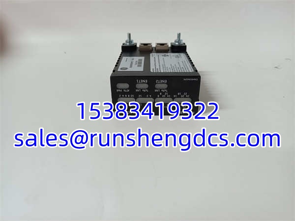
Turbine control cabinets are hostile environments for electronics, but the GE IS220PDIOH1B was built to survive them. This isn’t just a generic I/O card; it’s a specialized PDIO pack for the Mark VIe platform that handles the dirty work of interfacing field wiring with the controller. It consolidates 16 discrete inputs and 16 relay outputs into a single slot, cutting down on backplane congestion and simplifying the wiring harness in tight control panels.
Bottom line — you need this board because it handles the electrical noise that fries standard PLCs. The GE IS220PDIOH1B features industrial-grade isolation (≥250V AC) and programmable input filtering (0.1ms-100ms) to suppress contact bounce and EMI from nearby VFDs. With a mechanical relay life of over 1 million cycles and hot-swap capability, it minimizes downtime during maintenance. Just verify your terminal board type before ordering; this pack requires the correct TDBS or TDBT base to function.
QA/QC Transparency SOP
We don’t trust “pull-tested” claims. Every GE IS220PDIOH1B undergoes a rigorous 5-step validation to ensure it won’t fail during a critical turbine startup.
- Intake & Origin Verification: We inspect the PCB for thermal stress, check the DC-62 connector pins for wear, and verify the relay part numbers match OEM specs to avoid cheap clones.
- Live Functional Testing: The pack is installed in a live Mark VIe test rack. We force all 16 inputs and verify system recognition, then cycle all 16 relays to confirm mechanical actuation and feedback readback.
- Electrical Parameter Tests: Using a calibrated Fluke 115, we verify the 24VDC input thresholds and check relay contact resistance to ensure it’s under 100mΩ.
- Firmware/Config Verification: We read the pack ID and verify firmware compatibility with the target controller revision to prevent “Pack Mismatch” faults.
- Final QC & Anti-Static Packaging: After passing, the GE IS220PDIOH1B is sealed in a static-shielding bag with desiccant and packed with ESD-safe foam to prevent transit damage.
Field Engineer Gotchas
- Terminal Board Mismatch: The GE IS220PDIOH1B is not a standalone module. It plugs directly into a TDBS (Simplex) or TDBT (TMR) terminal board. If you try to force it into the wrong base, you will bend the DC-62 pins. Always verify the base part number (e.g., IS200TDBTH1A) before installation.
- Relay Contact Welding: This board uses 2A rated relays. If you’re driving solenoid valves or large contactor coils, check the inrush current. I’ve seen contacts weld shut because someone ignored the 1A inductive load limit. Use an interposing relay for anything over 1A inductive.
- Grounding the Shield: The GE IS220PDIOH1B shell is grounded, but your field cable shield must be terminated correctly at the terminal board. Floating shields in a turbine cabinet act as antennas for EMI. Ground the shield at the cabinet entry point, not at the pack.
- Hot-Swap Safety: Yes, it’s hot-swappable, but always kill power to the terminal block first. The pack can handle backplane removal, but pulling a live field wire can arc and destroy the output driver. I’ve fried two packs this way. Don’t be that guy.
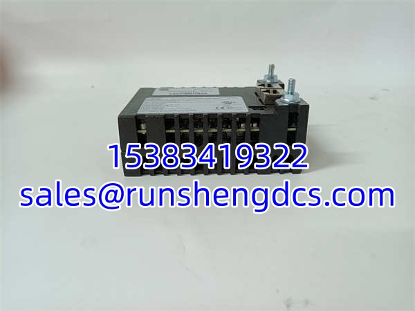
GE IS220PDIOH1B 336A5026ADP6
Application Scenarios
- Gas Turbine Fuel Valve Sequencing: The drives the solenoid valves for fuel gas skids, where fast response (<5ms) and reliable feedback are critical for safe combustion.
- Emergency Shutdown (ESD) Logic: Used for critical safety interlocks where the 16 discrete inputs monitor vibration, temperature, and pressure switches, triggering the relay outputs to trip the turbine.
- Auxiliary System Control: Managing lube oil pumps, cooling fans, and turning gear motors in the turbine lube oil skid, where high relay density saves rack space.
FAQ
Can I use this pack with a Mark VI (non-e) system?
No. The is strictly for the Mark VIe platform. The backplane bus and communication protocol are different. Do not attempt to force it into a Mark VI rack.
Does it support 125VDC inputs?
No. The is rated for 24VDC nominal (18-32V range). For 125VDC applications, you need a different PDIO variant or an external interface module. Check the datasheet before wiring.
How do I replace a failed relay on this board?
You don’t. The relays are surface-mounted and not field-serviceable. If a relay fails, replace the entire pack. Keep a spare in stock; downtime costs more than the board.
Is this pack TMR compatible?
Yes, but only when mounted on a TDBT terminal board. On a TDBS board, it operates in Simplex mode. Verify your system redundancy requirement before ordering.
What’s the max load per relay?
2A resistive, 1A inductive at 24VDC. Exceeding this will shorten relay life or cause contact welding. Always derate for inductive loads.
Do I need to configure anything in ToolboxST?
Yes. The is auto-detected, but you must verify the input filtering time and output pulse duration in the I/O configuration. Default settings might not match your field device requirements.