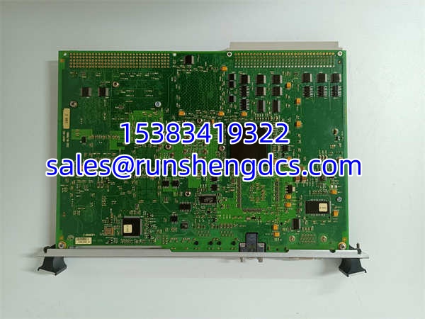

Description
Key Technical Specifications
| Parameter | IS215UCVGM06A | IS215UCVGH1A | VMIVME-7666-111000 |
|---|---|---|---|
| Product Type | UCV Controller Board | UCV Controller Board | Multifunctional I/O Module |
| System Series | Speedtronic Mark VIe | Speedtronic Mark VI | VME Bus I/O Module Series |
| Processor | Intel Celeron 1.06 GHz | Intel Celeron 650 (ultra-low voltage) | N/A (I/O module) |
| Memory | 1 GB SDRAM + 128 MB flash | 128 MB SDRAM + 128 MB flash | N/A |
| Ethernet Ports | 2 × 10/100BaseTX (RJ-45) | 2 × Ethernet (LAN1/LAN2) | N/A |
| Digital I/O | N/A | N/A | 16 DI + 16 DO |
| Analog I/O | N/A | N/A | 8 AI + 8 AO |
| Bus Interface | VME rack-mount | VME rack-mount | 32-bit VMEbus (ANSI/IEEE 1014-1987) |
| Input Voltage | N/A | N/A | 5V DC |
| Power Consumption | N/A | N/A | Max 5W |
| Form Factor | Single-slot VME | Single-slot VME | 6U VME (233.4mm × 160mm) |
| Operating Temperature | Not specified in source | Not specified in source | -40°C to +85°C |
| Additional Ports | 2 USB, 2 COM, VGA | 2 USB, 2 COM, SVGA, keyboard/mouse | Built-in self-test diagnostics |
| Country of Origin | USA | USA | USA |
| Warranty | 12 months (supplier-dependent) | 12 months (supplier-dependent) | 12 months (supplier-dependent) |
| HS Code | 8471.41 (Automatic data processing machines) | 8471.41 (Automatic data processing machines) | 8538.90 (Parts suitable for use with apparatus of heading 8537) |
Product Introduction
In a GE Speedtronic turbine control system, the UCV controller is the brain — it executes the real-time control algorithms that keep a gas or steam turbine running safely and efficiently. The IS215UCVGM06A and IS215UCVGH1A are two generations of GE’s UCV (Universal Control Versatile) controller boards, designed for the Mark VIe and Mark VI platforms respectively. The IS215UCVGM06A, built around an Intel Celeron 1.06 GHz processor with 1 GB SDRAM, represents the newer generation with significantly more processing power and memory for complex control strategies. The IS215UCVGH1A, using an Intel Celeron 650 processor with 128 MB SDRAM, is the established workhorse for Mark VI systems — and importantly, it is backward-compatible with earlier UCV controller versions, meaning it can directly replace older controllers without requiring a backplane upgrade.
Both UCV boards mount in standard VME racks and feature dual Ethernet ports for network communication — one port typically connects to the Universal Device Host (UDH) for configuration and peer-to-peer communication, while the second port operates on a separate IP subnet for Modbus or Ethernet Global Data (EGD) networks. This dual-port architecture provides critical network segmentation, keeping configuration traffic separate from real-time data exchange. Front-panel connectivity includes USB ports, COM ports, and video output (VGA/SVGA) for local diagnostics and configuration.
The VMIVME-7666-111000, on the other hand, is not a controller but a multifunctional I/O module that plugs into the same VME bus chassis. It provides 16 digital inputs, 16 digital outputs, 8 analog inputs, and 8 analog outputs — serving as the interface between the UCV controller’s logic and the physical world of sensors, actuators, and field devices. Its 32-bit VMEbus interface complies with the ANSI/IEEE 1014-1987 standard, ensuring compatibility with a wide range of VME-based industrial control systems. The built-in self-test diagnostics allow the module to verify its own health during startup and operation, alerting the controller to any I/O channel failures before they can cause a process upset.
Why does this matter for TCO? In turbine control, controller reliability directly translates to plant availability. A failed UCV board means the turbine trips — and in a combined-cycle plant, an unscheduled trip can cost hundreds of thousands of dollars in lost generation and restart costs. The IS215UCVGM06A’s 1 GB SDRAM and 1.06 GHz processor provide headroom for future control strategy upgrades, while the IS215UCVGH1A’s backward compatibility protects legacy installations from costly backplane replacements. The VMIVME-7666-111000’s wide -40°C to +85°C operating range and self-test diagnostics ensure that I/O failures are caught early, preventing false trips caused by degraded analog channels. For plants running GE turbine control systems, maintaining an inventory of verified spare UCV controllers and I/O modules is not optional — it is essential insurance against unplanned downtime. Bottom line — these boards are the computational and I/O backbone of your turbine control system. Treat them accordingly.
QA/QC Transparency SOP
Every IS215UCVGM06A, IS215UCVGH1A, and VMIVME-7666-111000 we ship goes through a five-step verification process. We do not simply pull them from a shelf and box them.
- Intake & Origin Verification: We trace each unit’s serial number and part number back to GE’s original manufacturing records. Counterfeit GE turbine control boards are not uncommon in the surplus market — we verify PCB silk-screen fonts, solder joint profiles, component date codes, and part number markings against known GE standards. For UCV controllers, we specifically verify the processor type and memory configuration match genuine GE specifications (e.g., IS215UCVGM06A must have Intel Celeron 1.06 GHz + 1 GB SDRAM; IS215UCVGH1A must have Celeron 650 + 128 MB SDRAM). Any unit with mismatched date codes, incorrect processor markings, or wrong memory capacity is rejected.
- Visual & Mechanical Inspection: We inspect every board for proper component seating, secure soldering, and absence of corrosion or physical damage. For UCV controllers, we verify that all front-panel ports (Ethernet, USB, COM, VGA/SVGA) are intact and undamaged. For the VMIVME-7666-111000, we verify the 6U VME form factor dimensions and check that the VME backplane connector pins are not bent or worn. We check the PCB for signs of overheating, cold solder joints, or physical damage. Any unit with mechanical defects is rejected.
- Functional Testing: For UCV controllers, we power up the board in a test VME rack and verify that it boots correctly, the processor is recognized, and the memory configuration matches specifications. We verify that both Ethernet ports link up correctly and that USB/COM ports are functional. For the VMIVME-7666-111000, we run the built-in self-test diagnostics to verify all 16 DI, 16 DO, 8 AI, and 8 AO channels are functional. We verify analog channel accuracy against known reference signals and check digital channel switching response. Any unit with failed diagnostics, non-functional ports, or out-of-spec analog channels is rejected.
- Fit-Check Verification: Each board is test-fitted into a standard VME rack to verify that the backplane connector aligns correctly, the board seats properly, and there is adequate clearance for adjacent modules. We verify hot-swap functionality by inserting and removing the board multiple times to confirm the connector pins are not bent or worn. Any unit with dimensional deviations or connector damage is rejected.
- Final QC & Anti-Static Packaging: After passing all tests, each board is coated with anti-static spray on exposed connectors, wrapped in Mil-Spec ESD shielding bags with desiccant packs, and placed in double-walled corrugated boxes with foam corner protectors. A signed QC certificate with test data (including processor verification, memory test results, port functionality checks, and I/O channel test results) is included in every shipment.
Field Engineer Gotchas
UCV Controller Generation Compatibility — Know Your System
The is a Mark VIe controller, while the is a Mark VI controller. Do not assume they are interchangeable — while the can replace earlier Mark VI UCV controllers without backplane changes, the is designed for the Mark VIe platform with different firmware and hardware requirements. Verify your system generation (Mark VI vs. Mark VIe) before ordering a replacement. Installing the wrong generation controller can result in firmware incompatibility and failure to boot.
Dual Ethernet Port Configuration — Subnet Separation is Critical
Both UCV controllers have two Ethernet ports that must be configured on separate IP subnets. The first port (typically LAN1) connects to the UDH for configuration and peer-to-peer communication. The second port (LAN2) operates on a different subnet for Modbus or EGD traffic. If both ports are configured on the same subnet, you will experience network conflicts, communication timeouts, and potentially controller instability. Use the Toolbox software to verify subnet configuration during commissioning.
For analog channel connections on the , use twisted-pair cable and ground the cable at the source device whenever possible. If the source device does not have a grounding option, ground the cable at the I/O module end. Improper grounding can introduce noise into analog channels, causing inaccurate readings and potentially triggering false trips. Additionally, verify that the module’s external transceiver power supply is correctly connected — the module itself is powered from the VME backplane (5V DC), but user transceivers may require external power.
UCV Controller Boot Time — Allow Full Startup Sequence
After inserting a UCV controller into the VME rack, allow sufficient time for the full boot sequence to complete. The controller must load firmware from flash, initialize memory, verify configuration settings from the Toolbox, and establish network communication before it can begin executing control logic. Removing or resetting the controller during boot can corrupt the firmware or configuration. Monitor the front-panel LEDs for boot status — do not assume the controller is ready just because it has power.
VME Backplane Power — Verify 5V DC Supply for VMIVME Modules
The draws power from the VME backplane (5V DC, max 5W). Verify that your VME chassis power supply can handle the cumulative power draw of all installed modules. An undersized power supply can cause voltage sag, leading to module instability or failure. During commissioning, measure the backplane voltage at the module connector to ensure it is within specification (typically 5V ±5%).
Spare Board Storage — Keep It Dry and Static-Free
All three boards have exposed connectors and sensitive electronic components. Store spare boards in their original ESD shielding bags with desiccant packs in a climate-controlled spare parts room (ideally 15–25°C, <60% RH). Do not store boards in unconditioned warehouses or near chemical storage areas. Exposure to humidity can cause connector corrosion, and exposure to corrosive vapors can degrade PCB traces over time. For UCV controllers, periodically power up spare units (at least annually) to prevent capacitor degradation and verify firmware integrity.
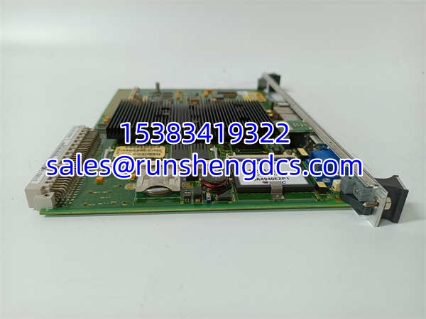
GE IS215UCVGM06A IS215UCVGH1A VMIVME-7666-111000
Application Scenarios
Gas Turbine Primary Control in Combined-Cycle Power Plants
In combined-cycle power plants, the (Mark VIe) or (Mark VI) serves as the primary controller for GE Frame 7FA and 9FA gas turbines. The UCV controller executes real-time control algorithms for fuel scheduling, inlet guide vane positioning, exhaust temperature control, and startup/shutdown sequencing. The dual Ethernet ports enable connection to the plant DCS for remote monitoring and to the UDH for local configuration. The provides the I/O interface for field devices such as pressure transmitters, temperature sensors, and valve positioners.
Steam Turbine Control in Cogeneration Facilities
Industrial cogeneration facilities use the to control extraction steam turbines that provide both power generation and process steam. The UCV controller manages extraction pressure control, load sharing between multiple turbines, and emergency trip logic. The ‘s 8 analog inputs monitor extraction pressure, exhaust pressure, and bearing temperatures, while its 16 digital outputs drive control valves and alarm indicators. The hot-swappable design allows controller replacement during online maintenance without requiring a turbine shutdown.
Compressor Station Control in Oil & Gas Pipelines
Pipeline compressor stations rely on GE turbine-driven compressors controlled by the . The controller manages compressor surge protection, speed control, and anti-surge valve positioning. The ‘s wide -40°C to +85°C operating range makes it suitable for outdoor compressor station installations where ambient temperatures can vary dramatically. The built-in self-test diagnostics alert operators to I/O channel failures before they can cause a compressor trip and pipeline shutdown.
Case Study: UCV Controller Failure Causes Gas Turbine Trip at a Combined-Cycle Plant
A combined-cycle power plant in Florida experienced an unscheduled gas turbine trip during normal baseload operation. The turbine tripped on “controller communication loss,” and the plant lost 150 MW of generation for 6 hours while the spare UCV controller was installed and commissioned. Post-incident investigation revealed that the controller had experienced a flash memory corruption, likely caused by a power supply transient during a nearby lightning strike. The corrupted firmware prevented the controller from booting, and the redundant controller (which was supposed to take over) had not been properly synchronized, so it also failed to assume control. The root cause was inadequate surge protection on the controller power supply and lack of regular redundant controller synchronization testing. After the incident, the plant installed dedicated UPS units for all UCV controllers, implemented monthly redundant controller failover testing, and increased their spare UCV controller inventory from one to two units. The total cost of the incident (lost generation + restart costs + equipment damage) exceeded 500,000 — compared to approximately 7,000 for a spare UCV controller.
FAQ
A: The is a Mark VIe UCV controller with an Intel Celeron 1.06 GHz processor and 1 GB SDRAM, designed for the newer Mark VIe platform. The is a Mark VI UCV controller with an Intel Celeron 650 processor and 128 MB SDRAM, designed for the legacy Mark VI platform. The is backward-compatible with earlier Mark VI UCV controllers and can replace them without backplane upgrades.
A: No. The is designed for the Mark VIe platform, while the is for the Mark VI platform. They use different firmware and have different hardware requirements. Installing a Mark VIe controller in a Mark VI system (or vice versa) will result in firmware incompatibility and failure to boot. Verify your system generation before ordering a replacement.
A: The is a multifunctional I/O module that provides 16 digital inputs, 16 digital outputs, 8 analog inputs, and 8 analog outputs. It plugs into a VME bus chassis and communicates with the UCV controller via the 32-bit VMEbus. It serves as the interface between the controller’s logic and field devices such as sensors, actuators, and valves.
A: The has an operating temperature range of -40°C to +85°C, making it suitable for harsh industrial environments including outdoor compressor stations and unconditioned control rooms.
Q: How many Ethernet ports do the UCV controllers have?
A: Both the and have two Ethernet ports (10/100BaseTX, RJ-45). The first port connects to the UDH for configuration and peer-to-peer communication, while the second port operates on a separate IP subnet for Modbus or EGD traffic.
A: Yes, the is designed for hot-swap operation in a VME rack. However, always follow GE’s documented hot-swap procedure to avoid momentary loss of control during replacement. Verify that the redundant controller is active and synchronized before removing the primary controller.
A: The draws power from the VME backplane (5V DC) with a maximum power consumption of 5W. Verify that your VME chassis power supply can handle the cumulative power draw of all installed modules.