
Description
Key Technical Specifications
| Parameter | Specification |
|---|---|
| Product Model | IS200TREGH1BEC |
| Manufacturer | GE (General Electric) |
| Product Type | Emergency Trip Terminal Board |
| Series | Speedtronic Mark VI |
| Application | Gas/steam turbine protection and control |
| Operating Voltage | 24 VDC |
| Power Consumption | 10 W |
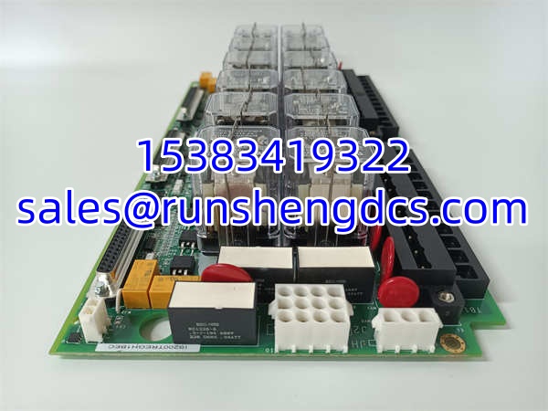
| Number of Surface Relays | 12 (9 for trip solenoid input voting) |
| Output Voltage | 0–10 V DC |
| Hot-Swappable | Yes |
| Protection Level | IP20 |
| Operating Temperature Range | -20°C to +60°C |
| Dimensions | 70 mm × 100 mm × 30 mm |
| Weight | Approximately 200 g |
| Country of Origin | USA |
| Warranty | 12 months (supplier-dependent) |
| HS Code | 8538.90 (Parts suitable for use with apparatus of heading 8537) |
Product Introduction
In a gas or steam turbine facility, the emergency trip system is the absolute last line of defense between a controlled shutdown and catastrophic mechanical destruction. When overspeed, loss of lube oil pressure, or a critical vibration alarm fires, the trip relays must drop out instantly — no hesitation, no firmware hang, no communication timeout. The GE IS200TREGH1BEC is an emergency trip terminal board engineered specifically for this purpose — it houses 12 surface relays (9 dedicated to trip solenoid input voting) and provides independent emergency overspeed protection linked directly to the VPRO (Variable Protection) board, ensuring that a trip command reaches the fuel stop valves and trip solenoids even if the primary controller has failed.
Unlike a standard I/O module that processes analog or digital signals for process control, the IS200TREGH1BEC is a dedicated trip relay board — its sole job is to execute trip logic reliably and instantly. The 12 surface relays are arranged in two rows of six, with 9 of them configured for 2oo3 (two-out-of-three) voting on trip solenoid inputs, ensuring that a single relay failure does not cause a spurious trip or, worse, a failure to trip. The board operates on 24 VDC with only 10W power consumption, and its hot-swappable design allows replacement during a running unit’s online maintenance window without requiring a full turbine shutdown.
The IS200TREGH1BEC integrates directly into GE’s Speedtronic Mark VI turbine control system, the industry-standard platform for gas and steam turbine management. Its compact 70mm × 100mm × 30mm footprint fits standard Mark VI I/O racks, and the IP20-rated enclosure is designed for indoor control room installation. The board’s VPRO linkage provides an independent overspeed protection path that is completely separate from the primary control logic — a critical redundancy feature required by API 670 and other turbine protection standards.
Why does this matter for TCO? In turbine protection, a single failed trip relay can mean the difference between a safe coast-down and a rotor overspeed event that destroys the entire turbine. The IS200TREGH1BEC’s 12-relay architecture with 2oo3 voting dramatically reduces the probability of both spurious trips (which cost hundreds of thousands in lost production) and failure-to-trip events (which can cost millions in equipment damage). For plants running GE Mark VI turbine control systems, keeping a verified spare IS200TREGH1BEC on hand is not optional — it is essential insurance. Bottom line — this board is the heartbeat of your turbine’s emergency protection system. Treat it accordingly.
QA/QC Transparency SOP
Every we ship goes through a five-step verification process. We do not simply pull it from a shelf and box it.
- Intake & Origin Verification: We trace each unit’s serial number and part number back to GE’s original manufacturing records. Counterfeit GE turbine control boards are not uncommon in the surplus market — we verify PCB silk-screen fonts, solder joint profiles, component date codes, and the part number markings against known GE standards. We specifically confirm the USA country of origin marking for genuine units and verify that the hardware revision matches genuine GE production records. Any unit with mismatched date codes or incorrect part number markings is rejected.
- Visual & Mechanical Inspection: We inspect every surface relay for proper seating, secure soldering, and absence of corrosion or physical damage. We verify that all 12 relays are present and correctly oriented in their two-row, six-per-row configuration. We check the PCB for signs of overheating, cold solder joints, or physical damage. We verify the IP20 enclosure integrity — no cracked housings, missing screws, or damaged mounting points. Any unit with mechanical defects is rejected.
- Relay Coil & Contact Testing: Using a relay test bench, we verify coil resistance for all 12 relays against GE’s specified range. We verify that each relay picks up and drops out at the correct voltage thresholds, and we verify contact continuity for both normally-open and normally-closed contacts. We specifically test the 9 trip-voting relays for proper 2oo3 voting logic behavior. Any unit with relay coil out-of-spec, contact welding, or voting logic failure is rejected.
- Fit-Check Verification: The board is test-fitted into a standard GE Mark VI I/O rack to verify that the backplane connector (P1) aligns correctly, the board seats properly, and there is adequate clearance for adjacent modules. We verify hot-swap functionality by inserting and removing the board multiple times to confirm the connector pins are not bent or worn. Any unit with dimensional deviations or connector damage is rejected.
- Final QC & Anti-Static Packaging: After passing all tests, the is coated with anti-static spray on exposed connectors, wrapped in Mil-Spec ESD shielding bags with desiccant packs, and placed in double-walled corrugated boxes with foam corner protectors. A signed QC certificate with test data (including relay coil resistance measurements, contact continuity results, and mechanical inspection findings) is included in every shipment.
Field Engineer Gotchas
Trip Voting Logic — Verify All 9 Voting Relays
The uses 9 of its 12 surface relays for 2oo3 trip solenoid input voting. During commissioning or after a board replacement, verify that all 9 voting relays are functional and that the voting logic is correctly configured in the VPRO board. A single failed voting relay can degrade the voting scheme from 2oo3 to 1oo2, increasing the risk of both spurious trips and failure-to-trip events. Use the Mark VI toolbox software to monitor individual relay status during testing.
Hot-Swap Procedure — Follow GE’s Sequence
The is hot-swappable, but improper removal or insertion can cause a momentary loss of trip protection. Always follow GE’s documented hot-swap procedure: first, verify that the redundant trip path is active; second, use the Mark VI toolbox to place the board in maintenance mode; third, remove the board slowly and evenly to avoid bending backplane pins; fourth, insert the replacement board firmly and verify that all status LEDs indicate normal operation before removing maintenance mode. Never yank the board out without placing it in maintenance mode first.
VPRO Linkage — Verify Independent Overspeed Path
The ‘s VPRO linkage provides an independent overspeed protection path separate from the primary Mark VI controller. During annual turbine protection testing, verify that the VPRO overspeed trip signal correctly actuates the trip relays on the . Do not assume the linkage is functional just because the primary controller is working — the whole point of VPRO is to provide protection when the primary controller has failed. Test the VPRO path independently during each outage.
24 VDC Supply — Monitor for Voltage Sag
The operates on 24 VDC with 10W power consumption. During a trip event, multiple relays may drop out simultaneously, causing a momentary current surge. Verify that your 24 VDC supply can handle this surge without voltage sag below the relay dropout threshold. A voltage sag during a trip event can cause relays to chatter or fail to drop out, delaying the trip. Use a dedicated, regulated 24 VDC supply for trip circuitry, separate from general control power.
IP20 Rating — Indoor Control Room Only
The has an IP20 protection rating, meaning it is designed for indoor control room installation only. It is not suitable for installation in the turbine enclosure, near the fuel gas manifold, or in any area with high humidity, conductive dust, or explosive atmospheres. If your Mark VI rack is located in a harsh environment, ensure the rack enclosure itself provides adequate protection (typically IP54 or higher for outdoor or washdown areas).
Spare Board Storage — Keep It Dry and Static-Free
Because the has exposed surface relays and backplane connector pins, proper storage is critical. Store spare boards in their original ESD shielding bags with desiccant packs in a climate-controlled spare parts room (ideally 15–25°C, <60% RH). Do not store boards in unconditioned warehouses or near chemical storage areas. Exposure to humidity can cause relay contact corrosion, and exposure to corrosive vapors (especially sulfur compounds) can degrade relay contacts over time, leading to contact resistance issues.
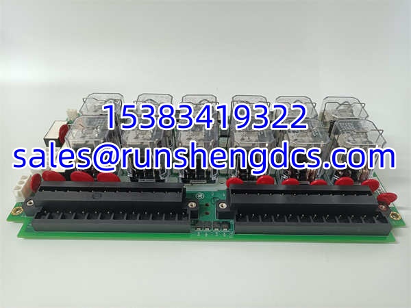
GE IS200TREGH1BEC
Application Scenarios
Gas Turbine Emergency Overspeed Protection in Combined-Cycle Power Plants
In combined-cycle power plants, the provides the emergency overspeed protection path for GE Frame 7FA and 9FA gas turbines. The 9 trip-voting relays implement 2oo3 voting on the trip solenoid inputs, ensuring that a single relay failure does not cause a spurious trip. The VPRO-linked overspeed protection operates independently of the primary Mark VI controller, providing a redundant trip path that meets API 670 requirements.
Steam Turbine Trip Circuit Termination in Cogeneration Facilities
Industrial cogeneration facilities use steam turbines for both power generation and process steam. The terminates the trip circuits for extraction steam valves, exhaust steam dump valves, and the main steam stop valve. The hot-swappable design allows relay board replacement during online maintenance without requiring a turbine shutdown, minimizing production losses.
Turbine Lube Oil Pressure Low Trip in Petrochemical Plants
Petrochemical plants with GE-driven compressors and pumps rely on the to execute lube oil pressure low trips. When the lube oil pressure drops below the setpoint, the trip relay drops out, closing the fuel stop valve and tripping the turbine. The 24 VDC operating voltage and 10W power consumption make the board compatible with standard plant control power systems.
Case Study: Failed Trip Relay Causes Turbine Overspeed Event at a Combined-Cycle Plant
A combined-cycle power plant in Texas experienced a gas turbine overspeed event during a load rejection. The turbine accelerated to 115% of rated speed before the backup mechanical overspeed device finally tripped the fuel stop valves, causing significant turbine blade damage. Post-incident investigation revealed that one of the 9 trip-voting relays on the had failed in the closed position due to contact welding, degrading the 2oo3 voting scheme to 1oo2. When the overspeed condition occurred, the remaining two voting relays dropped out correctly, but the welded relay prevented the trip signal from reaching the fuel stop valves in time. The root cause was relay contact degradation due to years of operation without relay testing. After the incident, the plant implemented annual relay coil resistance and contact continuity testing for all trip relays, and kept two spare boards on hand to facilitate rapid replacement.
FAQ
A: The is an emergency trip terminal board used in GE Speedtronic Mark VI turbine control systems. It houses 12 surface relays (9 for trip solenoid input voting) and provides independent emergency overspeed protection linked to the VPRO board for gas and steam turbine protection.
A: The has 12 surface relays arranged in two rows of six. 9 of these relays are dedicated to 2oo3 trip solenoid input voting, and the remaining 3 are used for other trip and status functions.
A: The operates on 24 VDC with a power consumption of 10W.
A: Yes, the is hot-swappable. However, always follow GE’s documented hot-swap procedure to avoid momentary loss of trip protection during replacement.
Q: What is the VPRO linkage?
A: The VPRO (Variable Protection) linkage provides an independent overspeed protection path that is completely separate from the primary Mark VI controller. The receives the VPRO overspeed trip signal and actuates the trip relays to shut down the turbine, ensuring protection even if the primary controller has failed.
Q: What is the operating temperature range?
A: The has an operating temperature range of -20°C to +60°C.
A: The has an IP20 protection rating, meaning it is designed for indoor control room installation only.
A: The is designed for the Speedtronic Mark VI series. For Mark VIe systems, GE offers the IS200TREGH1BDC and other updated trip terminal boards. Verify compatibility with your specific system generation before ordering a replacement.
A: Lead times vary from 2–5 days for in-stock units to 4–6 weeks if sourcing from overseas suppliers. For critical spares, we strongly recommend keeping at least one verified unit in your on-site inventory — the cost of a spare trip board is negligible compared to the cost of a turbine overspeed event.
Q: How do I verify the board is genuine GE?
A: Check the PCB silk-screen for GE’s font style and part number placement. Genuine GE boards have specific part number markings, a characteristic solder mask color, and component placement that matches GE’s assembly drawings. Verify the USA country of origin marking and the serial number against GE’s manufacturing records. Counterfeit boards often have mismatched date codes, incorrect relay spacing, or missing conformal coating.
A: Warranty terms vary by supplier. Reputable surplus dealers offer 12-month warranties covering defects in materials and workmanship, with professional testing and certification. Avoid suppliers offering less than 90 days — it is a red flag that they are not confident in their QC process. Always get the warranty terms in writing before purchasing, and request the QC test data for the specific unit you are buying.