
Description
Key Technical Specifications
| Parameter | Value |
|---|---|
| Product Model | IS200SDIIH1ADB |
| Alternate Part Number | MRP683026 |
| Manufacturer | GE (General Electric) |
| Product Type | Simplex Relay Output Terminal Board |
| Compatible System | GE Mark VI Speedtronic Turbine Control System |
| Compatible Processor Boards | VTUR, VCRC, VCC |
| Number of Relay Outputs | 12 Form-C (SPDT) dry contact relays |
| Configuration | Simplex (non-TMR); two boards can be paired for 24 total outputs |
| Relay Coil Indication | One LED per relay indicating coil voltage status |
| Onboard Suppression | None |
| Relay State Monitoring | Not supported |
| Terminal Connections | 36 screw terminals per side (both long edges) |
| Board Dimensions | 8.5″ x 8.1″ (approx. 216mm x 206mm) |
| Installation | Mounts in Mark VI I/O core rack, connects via ribbon cable |
| Country of Origin | USA |
Product Introduction
A failed relay output board in a turbine control system doesn’t just lose a few outputs — it can prevent critical trip signals from reaching solenoid valves, silence alarm notifications, or disable auxiliary relay circuits that protect the turbine from overspeed, overtemperature, or lubrication failure. The GE IS200SDIIH1ADB sits at the final output stage of the Mark VI Speedtronic control architecture, converting the processor’s logic decisions into physical dry contact closures that directly drive field devices responsible for turbine protection and plant alarming.
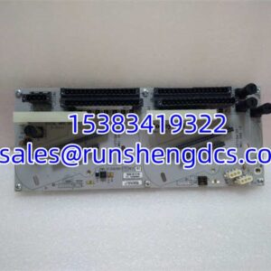
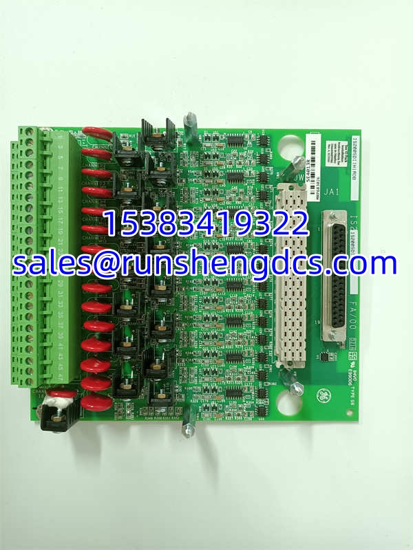
This is GE’s simplex relay output terminal board for the Mark VI Speedtronic turbine control system, designed for gas and steam turbine applications in mechanical drive and generator service. The board provides 12 Form-C (single-pole, double-throw) dry contact relay outputs, each with its own LED indicator showing coil voltage status — giving you immediate visual confirmation of which relays are energized without needing to access the HMI. The dry contact design means the relays provide a clean, voltage-free switching interface that can be wired to accept whatever field voltage your application requires, from 24 VDC solenoid circuits to 120 VAC alarm panels.
The IS200SDIIH1ADB connects to the Mark VI processor boards (VTUR, VCRC, or VCC) via a ribbon cable — no backplane slot required, as it mounts as a terminal board at the I/O rack edge. Each of the two long sides of the board has 36 screw terminals, providing generous wiring space for field connections. This is a simplex board, meaning it does not support TMR (Triple Modular Redundant) configurations on its own; however, two relay boards can be connected to the same processor for a total of 24 relay outputs if your application requires additional capacity.
Two hardware revisions exist: H1A and H1B. The H1A revision features higher-power relay contacts capable of switching heavier loads — verify which revision your system was originally configured with before ordering a replacement, as mixing revisions can result in relay contact ratings that don’t match your field load requirements. The board has no onboard arc suppression and no relay state monitoring feedback to the processor, so the control logic assumes the relay contact state matches the coil command. Bottom line — if your Mark VI system has lost relay output capability, this board restores the physical switching interface so turbine protection and alarming functions can operate correctly.
QA/QC Transparency SOP
- Intake & Origin Verification: Every GE IS200SDIIH1ADB is verified against GE part databases to confirm it’s a genuine Mark VI simplex relay output terminal board. We check the model number, revision marking (H1A or H1B), and MRP683026 alternate part number before it enters the test queue.
- Visual & Mechanical Inspection: The board is inspected for physical damage, corrosion, or burnt components. All 72 screw terminals (36 per side) are checked for secure mounting and proper threading. The ribbon cable connector is inspected for bent pins. Relay components are visually checked for signs of arcing or overheating.
- Relay Coil & LED Functional Test: Each of the 12 relay coils is energized individually via the ribbon cable interface, and we verify: (a) the relay audibly clicks (mechanical actuation), (b) the corresponding LED illuminates, and (c) the Form-C contacts switch correctly (common-to-normally-open closes, common-to-normally-closed opens). Contact resistance is measured to confirm low-resistance closure (<100mΩ).
- Contact Rating Verification: For H1A revision boards, we verify the relay contacts can handle the higher rated current specified for that revision by applying a test load and measuring voltage drop across the contacts. This ensures the replacement matches the original board’s switching capacity.
- Ribbon Cable Communication Test: The board is connected to a verified Mark VI processor board (VTUR/VCRC/VCC) and we verify the processor can command all 12 relays correctly. We confirm there is no cross-talk between relay channels — energizing one relay does not inadvertently affect adjacent relays.
- Final QC & Anti-Static Packaging: Passed boards are sealed in ESD-safe bags with desiccant, terminal screws are backed off to prevent thread damage, ribbon cable connector is capped, and a QC sticker with test date, technician ID, and revision (H1A/H1B) is applied.
Field Engineer Gotchas
- H1A vs. H1B Revision Matters: The H1A revision has higher-power relay contacts than H1B. If your field loads (solenoids, alarm circuits) draw more current than the H1B rating, substituting an H1B for an original H1A can result in premature relay contact failure or welding. Check your original board’s revision marking and match it exactly.
- Simplex Only — No TMR Support: The IS200SDIIH1ADB is a simplex board and does not support TMR configurations. If your Mark VI system is configured for TMR operation on relay outputs, this board alone will not work in that application. Verify your system’s redundancy configuration before ordering.
- No Onboard Suppression: The board has no arc suppression circuitry. If you’re switching inductive loads (solenoid coils, relay coils, motor starters), you must provide external suppression (flyback diodes, RC snubbers) at the field device to prevent contact arcing and premature relay failure. Verify external suppression is installed on all inductive loads.
- No Relay State Feedback: The board does not report relay contact position back to the processor — only coil voltage status is indicated via LED. The control logic assumes the contact state matches the coil command. If a relay contact welds or fails open, the processor will not detect it. For critical trip circuits, consider external contact monitoring.
- Ribbon Cable Orientation: The ribbon cable connecting to the VTUR/VCRC/VCC processor must be oriented correctly. Reversed or misaligned ribbon cables can damage the processor board or the terminal board. Verify pin 1 alignment before seating the connector.
- Terminal Torque Specifications: GE specifies proper screw terminal torque for Mark VI terminal boards. Over-torquing can strip threads; under-torquing causes high-resistance connections that overheat. Use a torque screwdriver set to GE’s specified value (typically 5-7 in-lbs for these terminals).
- Two-Board Pairing for 24 Outputs: If your application requires more than 12 relay outputs, two IS200SDIIH1ADB boards can be connected to the same processor. Verify the processor has sufficient output capacity and that your software configuration addresses both boards correctly.
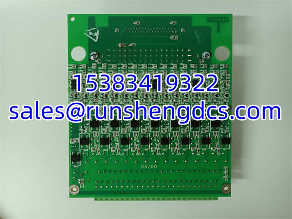
GE IS200SDIIH1ADB
Application Scenarios
- Gas Turbine Emergency Trip Circuit: In a GE Frame 7 gas turbine, the provides the physical trip output contacts that de-energize the fuel stop valve solenoid and the load gear trip solenoid when the Mark VI processor detects an overspeed, high exhaust temperature, or low lube oil pressure condition. The 12 relay outputs cover multiple redundant trip paths and auxiliary alarms. A failed relay board prevents trip signals from reaching the solenoids, potentially allowing the turbine to run away — a catastrophic failure mode. This is why keeping a verified spare on the shelf is critical for turbine protection systems.
- Steam Turbine Auxiliary Alarm & Control Outputs: In a steam turbine generator application, the drives auxiliary relays for bearing temperature alarms, vibration trip annunciation, gland steam pressure warnings, and condenser vacuum low alarms. Each of the 12 relay outputs connects to a separate alarm circuit in the plant DCS or annunciator panel. The LED indicators on the board allow operators to quickly identify which alarm condition is active during troubleshooting without navigating the HMI.
- Mechanical Drive Compressor Protection System: In a natural gas pipeline compressor station, a GE Mark VI system controls the gas turbine mechanical drive. The provides relay outputs for compressor surge detection trip, high discharge temperature alarm, seal gas differential pressure warning, and coupling vibration trip. The dry contact outputs interface with the compressor’s independent safety shutdown system, providing a hardwired backup to the electronic control logic.
FAQ
Q: What’s the difference between H1A and H1B revisions?
A: The H1A revision has higher-power relay contacts capable of switching heavier loads than the H1B revision. Verify which revision your system was originally configured with before ordering a replacement, as using the wrong revision can result in relay contact ratings that don’t match your field load requirements.
Q: Can I use this board in a TMR configuration?
A: No. The is a simplex board and does not support TMR (Triple Modular Redundant) configurations. If your Mark VI system requires TMR relay outputs, you need a different board type designed for TMR operation.
Q: How many relay outputs does this board provide?
A: 12 Form-C (SPDT) dry contact relay outputs. If you need more outputs, two boards can be connected to the same processor for a total of 24 relay outputs.
Q: Does this board have arc suppression?
A: No. The board has no onboard arc suppression circuitry. You must provide external suppression (flyback diodes, RC snubbers) at any inductive loads you’re switching to prevent contact arcing and premature relay failure.
Q: Does the processor know if a relay contact fails?
A: No. The board provides LED indication of relay coil voltage status, but there is no relay contact position feedback to the processor. The control logic assumes the contact state matches the coil command. For critical trip circuits, consider external contact monitoring.
Q: What processor boards is this compatible with?
A: The connects to VTUR, VCRC, or VCC processor boards in the GE Mark VI system via ribbon cable.
A: The Mark VI platform is a legacy product line from GE. The is a discontinued spare part. Surplus stock is available from secondary suppliers. For new installations, verify GE’s current turbine control platform offerings as a long-term replacement strategy.
Q: What’s the lead time for a replacement?
A: Surplus stock is typically available for 1-3 day shipment. Since the is a discontinued spare part used in critical turbine protection circuits, we strongly recommend keeping a verified spare on the shelf — a failed relay output board can prevent emergency trip signals from reaching the turbine.