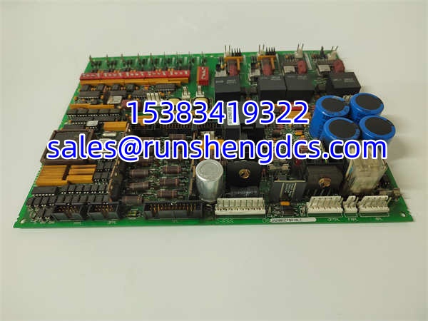

Description
Key Technical Specifications
| Parameter | Value |
|---|---|
| Product Model | DS200DCFBG1BLC |
| Manufacturer | GE (General Electric) |
| Product Type | DC Feedback Power Supply Board |
| Platform | Speedtronic Mark V |
| AC Input | 38-115 VAC |
| Input Frequency | 0-500 kHz (varies with input voltage) |
| DC Outputs | +5 VDC, ±15 VDC, ±24 VDC |
| Configuration | 12 jumpers, 7 DIP switches |
| Indicators | 2 LEDs + 1 neon indicator |
| Protection | 3 board fuses |
| Test Points | 5 integrated test points |
| Operating Temperature | -20 °C to +60 °C |
| Protection Class | IP20 |
| Compatible Drives | DC2000, AC2000, CB2000, ME2000, FC2000, EX2000 |
Product Introduction
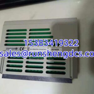
In GE Mark V drive cabinets, the DS200DCFBG1BLC is one of those boards that rarely gets attention until the control power disappears. It is not a processor, not a fieldbus card, and not a general-purpose PLC module. It is a DC feedback power supply board that sits inside Mark V drive assemblies and keeps the control electronics alive.
The DS200DCFBG1BLC accepts 38-115 VAC from the control power transformer and generates the control-level DC rails needed by the drive. It also supplies power to the enclosure cooling fan. The “DCFB” designation reflects its role in DC feedback and signal monitoring: the board includes AC and DC monitoring circuits, control-level power circuits, motor field power circuits, and driver circuits. With 12 jumpers and 7 DIP switches, it must be configured to match the specific drive application. Bottom line — it is a legacy but critical power and feedback board for GE Mark V turbine and drive systems.
QA/QC Transparency SOP
- Intake & Origin Verification: Confirm full part number DS200DCFBG1BLC, GE labeling, board revision suffix, and physical condition. Verify it belongs to the Mark V DS200 family, not an IS200 or DS3800 board.
- Live Functional Testing: Apply rated 38-115 VAC input in a controlled test setup. Confirm +5 VDC, ±15 VDC, and ±24 VDC outputs, fan supply output, and indicator behavior.
- Electrical Parameter Tests: Check fuse integrity, jumper and DIP switch settings, test point voltages, and connector condition. Inspect for burnt traces, swollen capacitors, or corrosion on legacy boards.
- Configuration Verification: Record all jumper and DIP switch positions before any adjustment. These settings are application-specific and must match the original drive configuration.
- Final QC & Anti-Static Packaging: Document measured outputs, indicator status, and configuration settings. Pack in anti-static material. For surplus units, state whether testing was performed with a compatible Mark V drive.
Field Engineer Gotchas
- DIP switches and jumpers are not optional. A replacement board with default or unknown switch settings can produce incorrect scaling, wrong feedback signals, or improper drive behavior. Photograph and record the original board before removal.
- Fuse failure can hide the real fault. The board uses three fuses. If a DC rail fuse opens, the drive may lose the ability to generate fault messages, making diagnosis harder.
- Neon indicator vs LED indicators. The neon lamp typically indicates a 115 VAC line fuse condition, while the LEDs indicate +24 VDC and -24 VDC fuse status. Do not interpret them as generic “power OK” lights.
- Legacy Mark V hardware is not plug-and-play across revisions. DS200DCFBG1BLC, DS200DCFBG1BJB, and DS200DCFBG1BNC are related but not automatically interchangeable. Verify the exact suffix and application manual before substitution.
- Surplus listings sometimes misclassify it as a processor module. It is a power and feedback board, not a CPU.
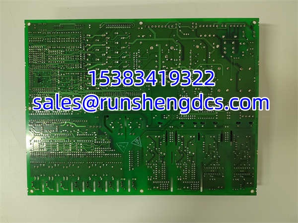
GE DS200DCFBG1BLC
Application Scenarios
- GE Mark V turbine control cabinets: Provides stable control power and DC feedback for speedtronic drive assemblies.
- DC2000/AC2000/FC2000 drive systems: Supplies control-level power and monitors armature, field, and AC line signals.
- EX2000 exciter applications: Supports control power and feedback monitoring in legacy excitation systems.
- Power plant and heavy industry maintenance: Used as a replacement board during Mark V drive refurbishment or emergency repair.
FAQ
It is a DC feedback power supply board for GE Speedtronic Mark V drives and turbine control systems.
What input voltage does it accept?
38-115 VAC, with a frequency range that can vary up to 500 kHz depending on input conditions.
What outputs does it provide?
Control-level DC power including +5 VDC, ±15 VDC, and ±24 VDC, plus enclosure fan power.
Which drives is it compatible with?
DC2000, AC2000, CB2000, ME2000, FC2000, and EX2000 applications.
Can I replace it with DS200DCFBG1BJB or DS200DCFBG1BNC?
Not automatically. These are related Mark V power boards, but the suffix and application configuration must be verified against the original equipment documentation.
Is this board still in production?
No. It is a legacy Mark V component and is typically sourced as surplus or refurbished stock.
What should I check before installing a replacement?
Verify the exact part number, record all jumper and DIP switch settings, check fuse condition, and confirm DC output voltages at the five test points before connecting it to the drive.