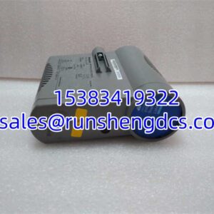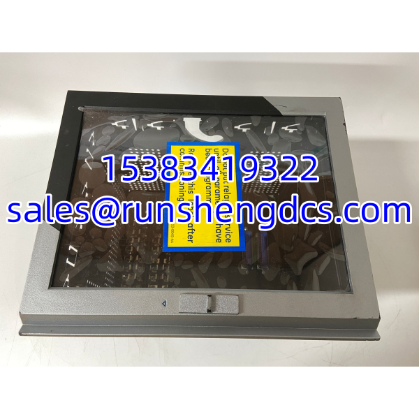

Description
Key Technical Specifications
| Parameter | Value / Notes |
|---|---|
| Part Number | 469-P5-HI-A20-E-H |
| Product Family | GE Multilin 469 / SR469 |
| Module Type | Motor management relay |
| Primary Use | MV / critical LV motor protection and monitoring |
| Power Supply Option | P5: typically 85–265 VAC or 90–300 VDC |
| Front Panel | HI: enhanced local display / HMI |
| Analog Outputs | A20: 4–20 mA retransmission option |
| CT Input | Typically used with 5 A phase CTs; verify with nameplate |
| RTD Inputs | Supports motor temperature monitoring, commonly Pt100 / Ni120 |
| Communication | Typically RS-232 front service port and RS-485 Modbus RTU |
| Operating Temperature | Typically around −20 °C to +60 °C; verify OEM datasheet |
| Mounting | Panel / MCC / switchgear door mounting |
Product Introduction
A motor trip that cannot be explained by a simple overload usually points to something deeper: unbalance, stalled rotor heating, bearing temperature rise, ground fault, or a protection relay that no longer matches the motor data. The GE 469-P5-HI-A20-E-H sits in that part of the control architecture as a dedicated motor management relay, not a general-purpose PLC card. It protects the motor, monitors thermal capacity, reads RTD temperatures, and sends key process values back to the DCS or PLC through 4–20 mA outputs.
Its practical value is consolidation. Instead of separate thermal-overload relays, temperature monitors, ammeters, and communication gateways, the 469 / SR469 platform combines protection logic, local diagnostics, and analog retransmission in one unit. The P5 supply option makes spare-part planning easier across sites with mixed AC/DC control power, while the HI panel gives operators a local view of alarms, setpoints, and motor status. Bottom line — it is a motor protection workhorse for legacy MV/LV installations, but only if the configuration actually matches the motor and the control system.
QA/QC Transparency SOP
- Intake & Origin Verification
Confirm the nameplate shows GE / GE Multilin, the full model 469-P5-HI-A20-E-H or SR469-P5-HI-A20-E-H, serial number, hardware revision, firmware revision, and manufacture date. Photograph the front panel, rear terminals, CT/RTD connections, and communication ports. Reject units with mismatched labels, missing nameplates, or physical damage. - Live Functional Testing
Power the relay from the correct control voltage. Verify that the front panel boots, menus respond, alarms clear, and the display shows expected motor variables. If possible, inject test current and confirm that measured current, thermal capacity, and protection logic respond correctly. - Electrical Parameter Tests
Check control power input, digital I/O continuity, RTD input continuity, and 4–20 mA output loop integrity. Use a multimeter or loop tester to confirm output scaling. Inspect terminals for corrosion, cracked insulation, burnt contacts, or loose screws. - Firmware/Config Verification
Connect to the front service port or RS-485 and read the firmware version, device settings, protection setpoints, CT ratio, RTD configuration, and communication address. Back up the configuration before making changes. Do not assume a used unit is pre-configured correctly for your motor. - Final QC & Anti-Static Packaging
Inspect for physical damage, verify mounting hardware, and confirm that all connectors are intact. Pack the relay in anti-static material with rigid protection. Include test status, firmware version, serial number, and a note that installation must follow site LOTO and CT safety procedures.
Field Engineer Gotchas
Firmware revision mismatch
Risk: The relay powers up, but the DCS cannot read data, setpoints look different, or Modbus registers do not match expectations.
Fix: Compare firmware revision, device type, and configuration against the existing system.
Blunt warning: A “same model number” 469 relay is not automatically a drop-in replacement if the firmware or configuration differs.
CT ratio and CT secondary wiring errors
Risk: Incorrect current measurement, false thermal overload, or protection misoperation.
Fix: Confirm CT ratio, 5 A secondary rating, polarity, and wiring against the motor nameplate and relay settings.
War story: A replacement 469 relay kept showing motor current far below actual load. The old relay had been configured for a different CT ratio. The hardware was fine; the setting was wrong.
RTD type and wiring mismatch
Risk: Bearing or stator temperature reads high, low, or fails open.
Fix: Confirm whether the motor uses Pt100, Ni120, 2-wire, 3-wire, or 4-wire RTDs, then match the relay configuration.
Bottom line: RTD errors are one of the most common reasons a “new” motor relay looks defective on first power-up.
Control power applied to the wrong terminals
Risk: Damage to the relay, blown fuses, or nuisance trips.
Fix: Verify that the现场 control supply matches the relay’s rated input before energizing.
Blunt warning: Do not assume P5 means “any voltage.” It covers a wide range, but wiring mistakes still destroy hardware.
4–20 mA output not mapped to DCS/PLC
Risk: The relay works, but the DCS shows zero, saturation, or wrong engineering units.
Fix: Confirm which variable is assigned to each analog output, then check span, polarity, loop power, and DCS scaling.
Reality check: The A20 option is useful, but only if the receiving system is configured to interpret it correctly.
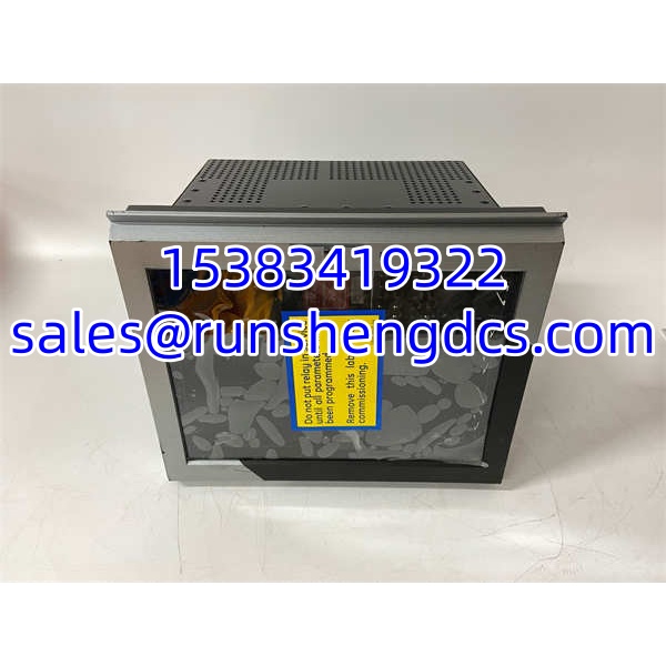
GE 469-P5-HI-A20-E-H
Application Scenarios
- Medium-voltage motor protection in power generation auxiliary systems, where thermal overload, stall, and negative-sequence protection must be coordinated with motor damage curves.
- Petrochemical pump and compressor trains, where motor current, thermal capacity, and bearing temperature must be visible to the DCS before a trip occurs.
- Mining or cement plant conveyors and fans, where frequent starts, high inertia, and harsh environments make thermal and stall protection critical.
- Water/wastewater pump stations, where remote motor status, RTD temperature, and analog retransmission reduce现场 troubleshooting time.
- Legacy MCC replacements, where an existing SR469 / 469 relay fails and the plant needs a verified spare without redesigning the protection scheme.
Anonymized case study
A chemical plant replaced a failed motor protection relay with a surplus 469-family unit. After installation, the DCS showed motor current at zero, even though the motor was running. Maintenance assumed the relay was defective. The real issue was twofold: the CT ratio setting did not match the installed 5 A CTs, and the 4–20 mA output was assigned to a different internal variable than the old relay. After correcting the CT ratio, reassigning the analog output, and verifying Modbus communication, the motor data matched the field instruments. The relay was not bad; the configuration was.
FAQ
Is 469-P5-HI-A20-E-H the same as SR469-P5-HI-A20-E-H?
They belong to the same GE Multilin 469 / SR469 motor management relay family, but do not assume full interchangeability without checking the nameplate, firmware, hardware revision, and configuration.
What does P5 mean?
P5 typically indicates a universal control power supply option, commonly rated around 85–265 VAC or 90–300 VDC. Verify the exact rating on the relay nameplate before energizing.
What does HI mean?
HI usually indicates an enhanced front panel with a larger local display for alarms, setpoints, diagnostics, and motor status.
What does A20 mean?
A20 typically indicates a 4–20 mA analog output option, used to retransmit motor variables such as current, thermal capacity, power, or temperature to a DCS or PLC.
Can I use this relay for any motor?
No. The relay must match the motor’s voltage class, CT ratio, RTD type, control power, protection requirements, and communication setup.
Will a surplus 469 relay work straight out of the box?
Not necessarily. A surplus unit may contain old settings, an incompatible firmware revision, or a different CT/RTD configuration. Back up the existing configuration before replacing, and verify the new unit before putting the motor back into service.
Is this relay still suitable for production use?
Yes, for existing 469 / installations where the hardware is verified and the configuration is supported. For new projects, confirm long-term spare availability and whether a current GE motor protection platform is required.