Description
Key Technical Specifications
- Product Model: 369-HI-R-M-0-0-0-E
- Manufacturer: GE Multilin
- Product Category: Motor Management Relay
- Current Input: HI Version (Direct 1–100A AC input via built-in Rogowski coils, no external CTs required)
- Communication: RS-485 Port with Modbus RTU Protocol
- Diagnostics: Enhanced Panel with Motor Health Reports and Start Data Logging
- Power Supply: 24–240V AC/DC (Wide range)
- Protection Functions: Overload, Short Circuit, Ground Fault, Phase Unbalance, Stall, Under/Over Voltage
- Metering Functions: Current, Voltage, Power, Power Factor, Energy, Frequency, Thermal Capacity Used
- Operating Temperature: -40°C to +85°C
- Mounting Style: Panel Mount / DIN Rail
Product Introduction
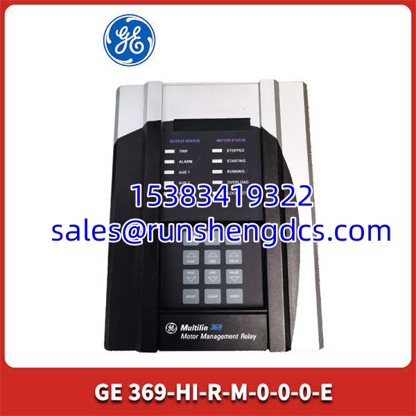
Replacing a tripped motor relay is frustrating when the new unit lacks the exact diagnostic capabilities of the failed part. The GE 369-HI-R-M-0-0-0-E eliminates this headache. As a high-current motor management relay, it directly accepts up to 100A without external current transformers, reducing panel wiring complexity and potential failure points.
This specific model features the “E” suffix, denoting an enhanced diagnostic panel. It records motor start data, tracks thermal capacity usage, and generates comprehensive motor health reports. Bottom line — it doesn’t just protect the motor; it provides the historical data needed to implement predictive maintenance and prevent catastrophic winding failures.
GE-369-HI-R-M-0-0-0-E
QA/QC Transparency SOP
Sourcing surplus motor protection relays requires rigorous validation. Here is our process for the 369-HI-R-M-0-0-0-E:
- Intake & Origin Verification: We verify the lot history and inspect the front panel display and buttons for physical wear.
- Live Functional Testing: Relays are powered up on a test bench. We use a primary injection kit to simulate phase currents and verify accurate metering and trip logic.
- Electrical Parameter Tests: We perform insulation resistance tests on the power inputs and verify the wide-range power supply regulation.
- Firmware/Config Verification: We connect via EnerVista 369 software to read the exact firmware revision and back up the current configuration.
- Final QC & Anti-Static Packaging: Units are sealed in ESD-safe shielding bags with anti-static foam to prevent transit damage.
Field Engineer Gotchas
- HI Input Misunderstanding: The “HI” designation means direct 1-100A input. Do not connect external CTs to this unit. Doing so will saturate the internal Rogowski coils and cause false trips or inaccurate metering.
- Modbus Address Conflicts: The “-M-” indicates Modbus RTU. If replacing a failed unit on an active network, ensure the new relay’s Modbus address matches the old one exactly, or the SCADA system will lose communication.
- EnerVista Software Compatibility: The enhanced “E” panel requires a compatible version of the EnerVista 369 setup software. Older PC software versions may not read the new diagnostic parameters correctly.
- Thermal Model Reset: After replacing a relay, the internal thermal replica model starts at zero. If the motor was recently running hot, you must manually adjust the initial thermal capacity parameter to prevent an immediate false overload trip.
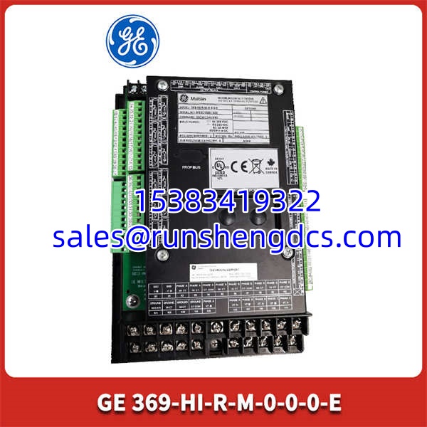
GE-369-HI-R-M-0-0-0-E
Application Scenarios
- Water/Wastewater Pump Stations: Protecting large vertical turbine pumps where motor health monitoring and start-data logging are critical for preventing cavitation damage.
- Oil & Gas Compressors: Providing advanced ground-fault protection and thermal modeling for critical pipeline motors in remote, unattended locations.
- Mining Conveyor Systems: Monitoring high-inertia loads and capturing oscillography data during nuisance trips to identify mechanical binding issues.
FAQ
Q: Does the “HI” version require external current transformers?
A: No. The HI version has built-in Rogowski coils for direct 1-100A measurement. External CTs are only required for currents above 100A.
Q: Will this replace a standard 369-HI-R-M-0-0-0-0?
A: Yes, it is fully backward compatible. The “-E” suffix simply adds the enhanced diagnostic panel and motor health reporting. The protection logic remains identical.
Q: Can I configure this relay without the proprietary software?
A: You can do basic setup via the front LCD panel, but configuring advanced protection curves, Modbus maps, and reading oscillography data requires the EnerVista 369 PC software.
Q: Is the Modbus TCP/IP protocol supported out of the box?
A: No. The “-M-” designation provides Modbus RTU over RS-485. Modbus TCP/IP requires an optional Ethernet communication module.
Q: My old relay had 12 RTD inputs. Does this model support them?
A: RTD inputs are an optional add-on. You must verify the physical presence of the RTD terminal block on the back of the relay or check the configuration via software before assuming it supports temperature monitoring.
Q: Are these units tested under actual motor load?
A: Full 100A load testing is impractical for surplus verification. We test primary injection accuracy, communication handshakes, and relay output contacts. Always perform a staged commissioning test during installation.