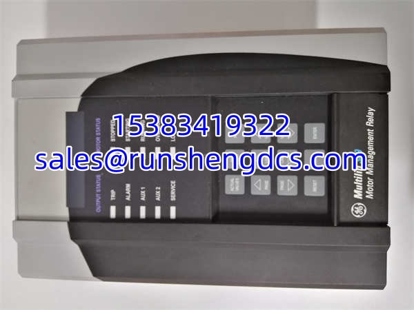
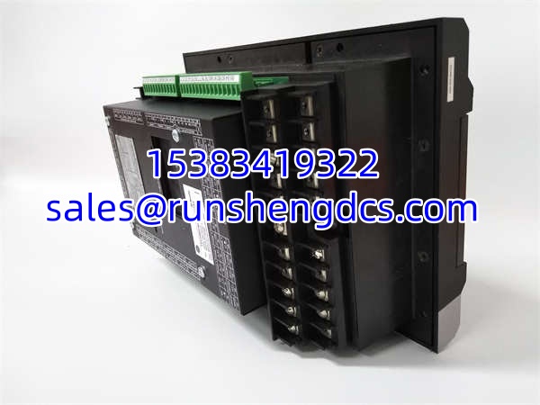

Description
Key Technical Specifications
| Parameter | Value |
|---|---|
| Product Model | 369-HI-R-M-0-0-0-0 |
| Manufacturer | GE Multilin |
| Product Type | Motor Management Relay |
| Current Input | 1-100A AC Direct (HI Version) |
| Communication | RS485 Modbus RTU (R-M Config) |
| Protection | Overload, Short Circuit, Ground Fault, Stall |
| Monitoring | Volts, Amps, Watts, PF, Energy, Hz |
| Event Recorder | 512 Events with Timestamps |
| Oscillography | 3 Waveforms, 16 Cycles Pre/Post Trip |
| RTD Inputs | Up to 12 (Optional, Verify Suffix) |
| Power Supply | 24-240V AC/DC Wide Range |
| Operating Temp | -40°C to +70°C |
Product Introduction
Motors don’t fail instantly; they degrade. The GE 369-HI-R-M-0-0-0-0 exists to catch that degradation before it becomes a catastrophic winding failure or bearing seizure. It’s not just a protective relay that trips on overcurrent; it’s a diagnostic platform that models motor thermal capacity, tracks start-up profiles, and logs 512 events with timestamps. When a motor trips, you don’t just reset it—you pull the oscillography and see exactly what happened 16 cycles before the fault.
You specify the 369-HI-R-M-0-0-0-0 when you need direct 1-100A input without external CTs and Modbus RTU integration for SCADA/DCS. The “HI” suffix means built-in Rogowski coil input up to 100A; the “R-M” confirms RS485 with Modbus protocol. Bottom line: if you’re still using thermal overloads and hoping for the best, you’re gambling with $50k motors. This relay gives you the data to move from reactive to predictive maintenance.
QA/QC Transparency SOP
- Intake & Origin Verification: Trace every 369-HI-R-M-0-0-0-0 to source. Verify the full suffix chain (HI-R-M-0-0-0-0). Check for physical damage, corroded terminals, or missing faceplate labels.
- Live Functional Testing: Install on GE test bench. Inject calibrated current/voltage. Verify trip curves match I²t thermal model. Confirm Modbus register read/write on all 512 event log entries.
- Electrical Parameter Tests: Megger test input-to-output isolation. Verify power supply draw across 24-240V range. Check relay output contact resistance (<100mΩ).
- Firmware/Config Verification: Read firmware version. Confirm compatibility with EnerVista 369 software (v6.x+). Backup existing settings if not factory reset.
- Final QC & Anti-Static Packaging: Visual inspection of DIN rail clips and terminal screws. Clean contacts. Seal in ESD-safe bag with desiccant. Include configuration sheet.
Field Engineer Gotchas
- Suffix Decoding: The 369-HI-R-M-0-0-0-0 suffix chain is non-negotiable. Risk: Ordering “369-HI-R-0-0-0-0” and getting no Modbus. Fix: Verify every position. “R” = RS485, “M” = Modbus. I’ve seen techs waste a week waiting for the right card because they assumed “R” meant Modbus.
- HI Input Wiring: The “HI” version uses direct 1-100A input, NOT CT secondary. Risk: Connecting 5A CT secondary to HI input and frying the Rogowski coil. Fix: Verify motor FLA is <100A before selecting HI. Use “LO” version with external CTs for higher currents.
- Modbus Address Conflicts: Default address is often 1. Risk: Two relays on the same RS485 bus with address 1. Fix: Set unique addresses BEFORE connecting to network. Use EnerVista to scan the bus first.
- Thermal Model Reset: The I²t thermal model doesn’t auto-reset on power cycle. Risk: Motor trips on “Thermal Overload” immediately after restart because memory wasn’t cleared. Fix: Use “Reset Thermal Memory” command in EnerVista or via Modbus after maintenance.
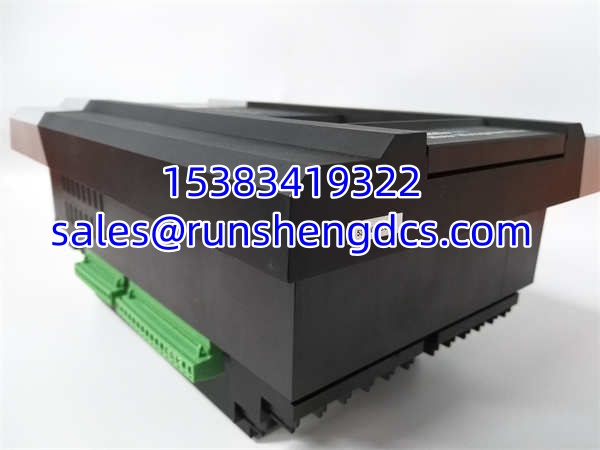
GE 369-HI-R-M-0-0-0-0
Application Scenarios
- Pump & Fan Protection: Monitoring cavitation, bearing wear, and locked rotor conditions. The 369-HI-R-M-0-0-0-0 tracks start time vs. locked rotor time to prevent insulation damage.
- Conveyor & Crusher Motors: High-inertia loads with frequent starts. Thermal capacity tracking prevents nuisance trips while protecting against genuine overloads.
- HVAC & Cooling Towers: Modbus integration for BMS. Remote monitoring of motor health, energy consumption, and power factor without pulling separate metering.
FAQ
Can I use this with external CTs?
No. The “HI” in 369-HI-R-M-0-0-0-0 means direct 1-100A input. For external CTs, you need the “LO” version (e.g., 369-LO-R-M-0-0-0-0). Don’t mix them up.
Does this support Ethernet?
Not natively. The “R-M” suffix is RS485 Modbus RTU only. For Ethernet, you need the “-E” suffix option or an external protocol converter. Check your network architecture before ordering.
What software do I need?
EnerVista 369 (free from GE). Required for configuration, oscillography viewing, and firmware updates. The 369-HI-R-M-0-0-0-0 has a front-panel LCD for basic monitoring, but full setup requires the PC tool.
Can I hot-swap this relay?
No. It’s a protection device. Removing it de-energizes the motor control circuit. Plan for a shutdown. Use the 511 Lockout/Test module if you need safe isolation during maintenance.
How many RTD inputs does it have?
Up to 12, but verify your suffix. The base 369-HI-R-M-0-0-0-0 may have 0 RTDs. The 7th digit in the suffix specifies RTD count. Check the nameplate or order confirmation.
Is this compatible with my old 369 settings?
Maybe. Firmware revisions change parameter names and scaling. Always backup old settings first. Use EnerVista’s “Compare” function to map old parameters to new. Don’t assume 1:1 mapping.
What’s the max cable length for RS485?
4000ft (1200m) at 9600 baud. Use shielded twisted pair, single-point ground. Don’t daisy-chain power. The 369-HI-R-M-0-0-0-0 has built-in termination resistors—enable them at the end of the bus only.