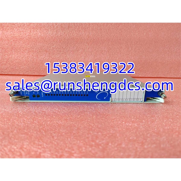

Description
Key Technical Specifications
| Parameter | Value / Notes |
|---|---|
| Product Model | 3500/33 149986-01 |
| Brand | Bently Nevada |
| Product Family | 3500 Machinery Monitoring & Protection System |
| Module Type | Relay output module |
| Channel Count | 16 channels |
| Front Panel P/N | 149986-01 |
| Associated Rear Board | 149992-01 (verify on physical unit) |
| Rack Compatibility | 3500/05 frame |
| Configuration | Via 3500 rack configuration software |
| Application Class | Machinery protection, alarm, trip output |
| Standards Context | Used in API 670-class machinery protection applications |
| Hot-Swap | 3500 modules generally support hot-swap; verify OEM procedure |
Product Introduction
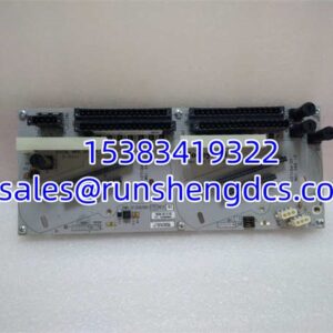
A 3500 rack can look healthy on the display while its trip outputs quietly fail to operate. The Bently Nevada 3500/33 149986-01 is the part that closes that gap: a 16-channel relay module used to convert 3500 monitoring and protection logic into physical relay outputs for alarms, trips, permissives, and machine-shutdown interfaces.
In a typical 3500/05 rack, monitoring modules such as vibration, position, speed, or temperature monitors evaluate the process condition. The 3500/33 then provides the relay interface that drives field circuits, safety systems, DCS inputs, or ESD/ETS logic. Bottom line — it is not a sensor input card. Its job is to make sure that when a monitor says “trip,” the relay actually moves.
QA/QC Transparency SOP
- Intake & Origin Verification
Confirm the full model 3500/33 and front panel P/N 149986-01. Record the rear board P/N, serial number, date code, and any revision markings. Inspect the backplane connector, relay indicators, front-panel labeling, and mounting hardware for bent pins, corrosion, cracked housings, or signs of overheating. - Live Functional Testing
Install in a known-good 3500/05-compatible test frame only if the test environment supports safe relay-module testing. Verify that the rack recognizes the module, that channel status indicators behave correctly, and that the module does not report permanent faults. - Relay Channel Test
Force or simulate alarm/trip states through the 3500 configuration environment where available. Confirm each relay channel changes state as expected. Do not assume all 16 channels are functional just because the module powers up. - Configuration Verification
Read the module identity, channel assignments, and trip/alarm logic settings. Compare them against the target machine protection configuration. A physically correct 3500/33 can still misbehave if the channel mapping, latch behavior, or firmware expectations do not match the existing rack. - Final QC & Anti-Static Packaging
Clean the module exterior, protect the backplane connector, and pack in ESD-safe material. Include a test note covering power-up status, relay channel test results, rear board P/N, serial number, and any observed faults. For surplus protection hardware, photos of both front and rear labels are more useful than a generic “tested good” claim.
Field Engineer Gotchas
Front panel vs. rear board mismatch
Risk: The front panel says 149986-01, but the rear board or internal assembly does not match the expected 3500/33 configuration.
Fix: Check both the front panel P/N and the rear/backplane P/N before installation.
Blunt warning: Surplus listings sometimes mix display modules, relay modules, and rear boards. If the rear board is wrong, the module may not seat, communicate, or drive relays correctly.
Wrong module substitution
Risk: A technician installs a 3500/32 or display module where a 3500/33 is required.
Fix: Confirm the module function. The 3500/33 is a 16-channel relay module, not a 4-channel relay module, not a display, and not a vibration monitor.
War story: A replacement module fit the slot and powered up, but the trip outputs never operated. The part looked similar, but the channel count and function did not match the protection logic. Always verify function, not just physical fit.
Relay output wiring errors
Risk: Field wiring is connected to the wrong relay contact, so the DCS sees the opposite state or the trip circuit never closes.
Fix: Trace each relay channel from the 3500 configuration to the terminal block. Verify NO/NC contact assignment, common points, and external supply polarity.
Bottom line — relay modules fail more often in wiring than in silicon.
Configuration not restored after swap
Risk: The replacement module powers up, but the machine protection logic does not behave the same.
Fix: Reload or verify the 3500 rack configuration, including channel assignments, alarm/danger setpoints, latch behavior, and trip logic.
Do not assume a spare 3500/33 is pre-configured for your machine.
Hot-swap without procedure
Risk: Pulling or inserting the module in a live protection rack without following the OEM procedure can disturb relay states.
Fix: Follow the Bently Nevada hot-swap and maintenance procedure for the specific rack and software version.
If the machine is running and trip logic is active, treat the swap as a protection-system event, not a routine card change.
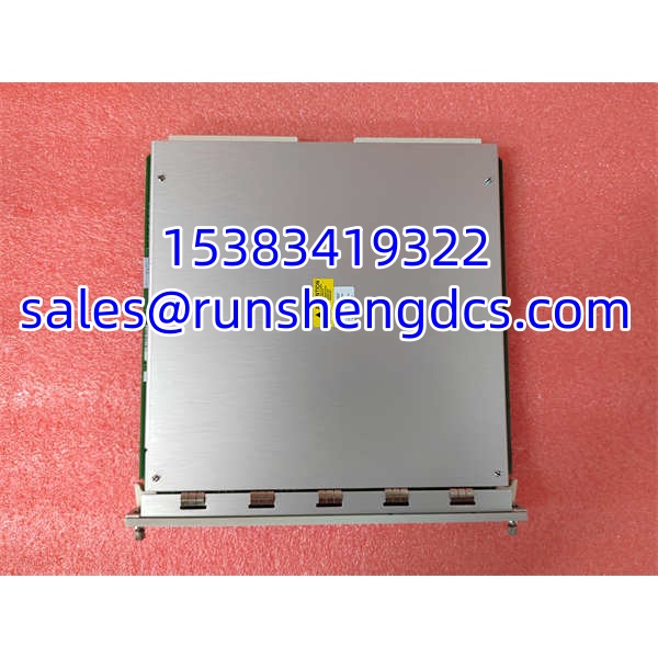
BENTLY 3500-33 149986-01
Application Scenarios
- Steam turbine protection systems
Used to convert vibration, axial position, speed, or temperature alarms into relay outputs that feed the DCS, ETS, or machine-trip logic. - Centrifugal compressor packages
Applied in API 670-class protection racks where multiple monitoring modules must drive alarm and trip relays for shutdown interlocks. - Gas turbine auxiliary skids
Used where relay outputs from the 3500 rack must interface with plant safety systems, local panels, or remote I/O. - Power generation rotating equipment
Applied on generators, exciters, gearboxes, and large motors where continuous protection and alarm annunciation are required. - Legacy 3500 rack maintenance
Used as a spare relay module when the installed base still depends on 3500/33 channels and a full system upgrade is not scheduled.
Case study — anonymized
A refinery compressor rack showed a vibration alarm on the display, but the field trip relay never operated. Maintenance replaced the monitoring module first. The alarm still appeared, but the relay remained inactive. The real fault was in the 3500/33 relay channel: the output was configured correctly in the display, but the relay contact wiring had been moved during a previous panel modification. Once the relay channel was traced from the module to the terminal block and the wiring was corrected, the trip output operated as designed. Lesson: in protection systems, trust the signal path — display alarms do not prove relay output.
FAQ
Is the 3500/33 149986-01 a vibration monitor?
No. It is a 16-channel relay module for the Bently Nevada 3500 system. It provides relay outputs; it does not directly monitor vibration, position, or temperature.
What does 149986-01 refer to?
It is the front panel part number associated with the 3500/33 relay module. The rear/backplane P/N is typically 149992-01, but verify on the physical unit before installation.
Will any 3500/33 drop into my rack?
Not automatically. The module must physically fit the 3500/05 frame, but you also need to verify rear board P/N, firmware/configuration compatibility, channel assignments, and trip logic before installation.
How many relay channels does it have?
The 3500/33 is a 16-channel relay module.
Can I use this for API 670 machinery protection?
Yes, in the context of a complete 3500 protection system. The 3500/33 provides relay outputs used in machinery protection applications, but the overall protection function depends on the monitoring modules, configuration, sensors, and relay wiring.
Does it support hot-swap?
3500 modules generally support hot-swap, but the exact procedure depends on the rack, power supply, configuration software, and protection logic. Verify the OEM procedure before removing or inserting the module in a live system.
What should I check before buying a surplus 3500/33 149986-01?
Ask for photos of the front and rear labels, serial number, rear board P/N, power-up test results, relay channel test results, and any configuration records. If the supplier cannot confirm those details, do not install it directly into a live protection rack.