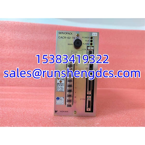

Description
Key Technical Specifications
| Parameter | Specification |
|---|---|
| Part Number | CACR-02-TE1K |
| Product Type | AC Servo Drive (SERVOPACK) |
| Product Series | Sigma-7 (as listed by distributor sources) |
| Rated Output | 2 kW |
| Peak Output | 3 kW |
| Rated Input Voltage | 230 VAC |
| Peak Current | 16 A |
| Control Modes | Position, Speed, Torque |
| Response Bandwidth | 500 Hz |
| Overload Capacity | 200% |
| Position Accuracy | ±0.001 mm (system-dependent) |
| Speed Accuracy | ±0.01% |
| Torque Accuracy | ±0.1% |
| Dimensions | 200 × 150 × 60 mm |
| Weight | ~3 kg |
| Mounting | Wall-mount or panel-mount |
| Communication Interfaces | RS-232 / RS-485 / CAN (as listed by distributor sources) |
| Protection Features | Overcurrent, overheat, overvoltage protection (as listed by distributor sources) |
Product Introduction
A CNC axis starts overshooting at rapid traverse, and the root cause isn’t the encoder — it’s a servo drive whose tuning parameters drifted after a power-cycle fault. The YASKAWA CACR-02-TE1K is the 2 kW servo amplifier that sits between your motion controller and the servo motor, closing the position, speed, and torque loops with a 500 Hz response bandwidth. It accepts 230 VAC input, delivers up to 16 A peak current, and supports 200% overload for short-duration acceleration demands — the kind of margin you need when a spindle needs to reach speed in milliseconds, not seconds.
The CACR-02-TE1K belongs to YASKAWA’s Sigma-7 SERVOPACK family, a platform widely deployed in machine tools, packaging lines, textile machinery, and material-handling systems. It supports auto-tuning to match motor inertia and mechanical stiffness, reducing commissioning time compared to manual gain adjustment. Built-in diagnostics flag overcurrent, overheat, and overvoltage conditions before they cascade into motor or mechanical damage. Communication options reported for this series include RS-232, RS-485, and CAN, though the exact interface depends on the specific suffix and option board fitted. As with any surplus servo drive, always verify the compatible motor model and encoder type — a mismatched encoder protocol is the fastest way to get a drive that powers up but refuses to run.
QA/QC Transparency SOP
- Intake & Nameplate Verification — Serial number, suffix code, and hardware revision logged. Visual inspection for burnt traces, swollen capacitors, corroded connector pins, and damaged terminal blocks. Cross-reference suffix against YASKAWA part-number conventions to confirm rated voltage and option configuration.
- Power-Up & Self-Test — Drive energized at rated 230 VAC with no motor connected. Internal self-diagnostics verified; no alarm codes on power-up. DC bus voltage measured and confirmed within specification. Control power and main power circuits checked independently.
- Motor-Connected Functional Test — Drive connected to a compatible YASKAWA servo motor on a test bench. Position, speed, and torque modes exercised via pulse-train and analog command inputs. Auto-tuning routine executed and gain parameters logged. Overshoot, settling time, and following error measured against baseline.
- Protection & Fault Simulation — Overcurrent, overvoltage, and overheat protection verified through controlled fault injection. Regenerative resistor operation confirmed. Alarm history cleared and re-verified clean after reset.
- Final QC & Packaging — Drive removed from test bench, connectors capped, sealed in ESD bag with desiccant. Test report including alarm history, gain parameters, and measured DC bus voltage included with shipment.
Field Engineer Gotchas
- Suffix Code Determines Compatibility — The “TE1K” suffix encodes input voltage phase, encoder type, and communication options. Substituting a drive with a different suffix (e.g., TE1K vs. TF1K) can result in encoder protocol mismatch or incorrect input voltage rating. Always match the suffix to the original nameplate or the motor’s encoder type.
- Encoder Type Must Match — Sigma-7 drives support incremental and absolute encoders, but the drive must be configured for the correct encoder protocol. A drive configured for an incremental encoder will not run an absolute-encoder motor without a parameter change — and vice versa. Check parameter Pn002 (encoder type) after any drive swap.
- Regenerative Resistor Sizing — The built-in regenerative resistor is sized for a specific inertia ratio and duty cycle. High-inertia vertical axes or frequent deceleration cycles can overheat the internal resistor. If you see repeated “regenerative overload” alarms (A.320), install an external regenerative resistor and update the parameter accordingly.
- Auto-Tuning Is Not a Silver Bullet — Auto-tuning works well for rigid, low-backlash mechanisms. On belt-driven axes or systems with significant backlash, auto-tuning can produce aggressive gains that cause audible hunting or mechanical wear. Always verify the tuned gains manually and reduce stiffness if the mechanism is compliant.
- 230 VAC Input — Single vs. Three-Phase — The CACR-02-TE1K is rated for 230 VAC, but some variants accept single-phase input while others require three-phase. Wiring a three-phase-only drive to single-phase input will trip an undervoltage or input-phase-loss alarm on power-up. Verify the input phase requirement on the nameplate before connecting power.
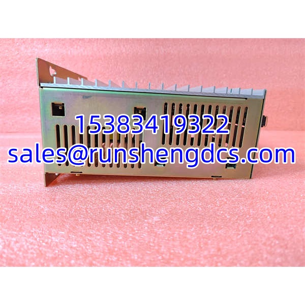
YASKAWA CACR-02-TE1K
Application Scenarios
- CNC machine axis drive — A 2 kW Sigma-7 drive controls the X-axis servo motor on a milling machine. The 500 Hz bandwidth ensures tight following error during rapid traverse, while the 200% overload capacity handles the inertia of a heavy gantry during acceleration.
- Packaging machine indexing — A rotary indexing table uses the CACR-02-TE1K in position mode with electronic gearing. The drive’s auto-tuning compensates for varying product loads on the table, maintaining consistent index accuracy across batches.
- Web-fed printing press tension control — In torque control mode, the drive regulates the torque on a unwind roller, maintaining constant web tension as the roll diameter decreases. The ±0.1% torque accuracy prevents web breaks during high-speed operation.
FAQ
A: 2 kW rated output, 3 kW peak, with a 16 A peak current rating at 230 VAC.
Q: Which control modes does this drive support?
A: Position, speed, and torque control modes. The mode is selected via parameter setting and command input type.
A: No. The drive must be matched to a compatible Sigma-series motor with the correct encoder type (incremental or absolute) and power rating. Check the drive nameplate and the motor datasheet for compatibility.
Q: Does this drive support auto-tuning?
A: Yes. The Sigma-7 SERVOPACK includes auto-tuning functionality that measures motor inertia and mechanical stiffness, then sets gain parameters automatically. Manual gain adjustment is still recommended for compliant or high-backlash mechanisms.
Q: What communication interfaces are available?
A: Distributor sources list RS-232, RS-485, and CAN as available interfaces for this series. The exact interface depends on the specific suffix and any fitted option board. Verify against the unit nameplate.
A: Availability varies by region and distributor. Most units on the market are surplus or refurbished. Always request a test report and verify firmware revision before purchase.
Q: What alarms should I watch for during commissioning?
A: Common alarms include A.710 (overcurrent), A.320 (regenerative overload), A.400 (overheat), and A.C00 (encoder error). The alarm history can be read via the drive’s LED display or through the communication interface.