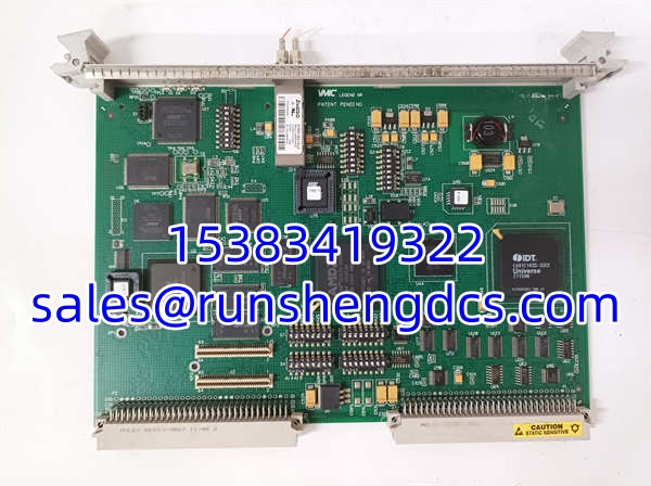
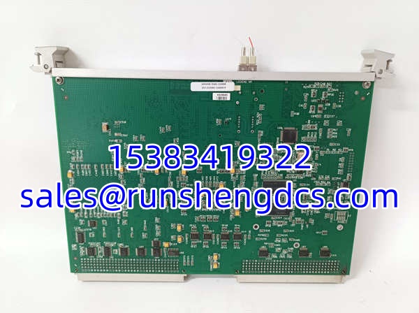

Description
Key Technical Specifications
- Form factor: Single‑slot 6U VME Eurocard, VME64 compliant (A16/A24/A32, D08/D16/D32)
- On‑board memory: 128 MB SDRAM
- Fiber interface: Dual LC multimode, 2.125 Gbaud
- Topology: Ring or star; redundant dual‑fiber mode supported
- Max nodes: 256 nodes per reflective memory network
- Latency: Sub‑1 µs per‑node hardware mirroring
- Throughput: Non‑redundant: 43 MB/s (single longword) up to 174 MB/s (64‑byte burst); redundant: 20–87 MB/s
- Packet size: Dynamic 4 – 64 bytes
- Interrupt: Hardware interrupt forwarding across fiber, VME IRQ levels 1–7
- DMA: Dual independent DMA engines
- Fiber distance: Multimode ≤300 m; single‑mode variant (-111000) up to 10 km
- Backplane power: +5 VDC from VME backplane; max 5 A @5 V (25 W), typical ~15 W
- Operating temperature: 0 °C to +55 °C (commercial grade, forced air)
- Storage temperature: −40 °C to +85 °C
- Humidity: 20–80%, non‑condensing
- Typical MTBF: 163,995 hours (Bellcore calculation @40 °C)
- Weight: ~0.7 kg
Product Introduction
Real‑time simulation and turbine control systems depend entirely on reflective memory. If one VMIVME‑5565 node fails, the shared memory ring breaks and all synchronized chassis lose time‑coherent data. No new factory builds exist, and full migration to modern RFM or Ethernet‑based real‑time networks requires lengthy outage planning. This VME card maps a block of local physical memory. Any write from the local VME CPU is captured by onboard hardware, broadcast over fiber, and replicated at the identical address on every other node in the ring. This all happens in hardware, independent of OS protocol stacks. It does not execute user logic or provide analog/digital field I/O.
Shelf‑aged boards commonly suffer from dried electrolytic capacitors and degraded optical transceivers. Unlike Ethernet, there is no TCP retransmission; integrity relies on built‑in hardware CRC checks. Under steady burst traffic, jitter remains well below 200 ns. Bottom line — it works, but full ring testing with matched firmware and optical power measurement is mandatory before live commissioning.
QA/QC Transparency SOP
- Intake & Origin Verification. Match primary part number, alternate PN 332‑015565‑110000 and serial number against source documentation. Inspect PCB for bulging capacitors, solder cracks, LC port contamination, backplane pin corrosion. Photograph label, component side and fiber connectors for traceability. Reject units showing liquid intrusion or burned transceivers.
- Live Functional Testing (Comms, Memory, Load). Install two or more cards in matched VME test chassis, connect fiber ring. Apply VME backplane power. Run continuous memory write/read burst traffic across the ring for minimum 4 hours. Verify cross‑node interrupt forwarding, CRC error counters stay zero, measure optical transmit/receive power. Test both normal and redundant fiber modes.
- Electrical Parameter Tests (Megger, Continuity). De‑energize crate. Run 500 V Megger between VME signal pins and chassis ground. Insulation resistance >100 MΩ required. Verify every P1/P2 backplane pin continuity with a Fluke 87V.
- Firmware/Config Verification (Readout & Backup). Read onboard FPGA/firmware revision. Save bitstream offline. Flag revisions known to cause ring drops or interrupt misfires; cross‑reference against site’s validated firmware matrix. All nodes on one ring must run compatible firmware.
- Final QC & Anti‑Static Packaging. Recheck front‑panel status LEDs, inspect LC ports for dust, install dust caps. Place board in conductive ESD bag, foam edge guards, rigid shock‑resistant carton. Attach unique burn‑in test report ID externally.
Field Engineer Gotchas
- Firmware/FPGA Rev Mismatch. Risk: Nodes with mismatched firmware cannot join the same ring. Ring keeps dropping or some nodes see stale data with no obvious fault alarm. Solution: Every node on the reflective memory ring must run compatible FPGA/firmware. One simulator team swapped one card without checking revisions; the whole ring kept resetting for three hours.
- Optical port contamination. Risk: Dust, oil or scratches on LC transceiver faces reduce receive power. Intermittent CRC errors appear under vibration or temperature swings. Errors may come and go without being logged consistently. Solution: Always clean fiber ports and patch cords with approved fiber cleaner before installation; fit dust caps when not connected.
- No true hot‑swap. Risk: Although the VME crate may allow hot removal, pulling one node breaks the fiber ring. All remaining nodes lose synchronization. Solution: Plan replacement during downtime or use redundant dual‑fiber ring topology for fault‑tolerant systems.
- Capacitor aging on surplus hardware. Risk: Board boots fine and passes quick 5‑minute test. After thermal soak, memory corruption or transceiver lockups start. Visual inspection may show no bulging caps. Solution: Short power‑on tests are insufficient; multi‑hour burn‑in under traffic load is required.
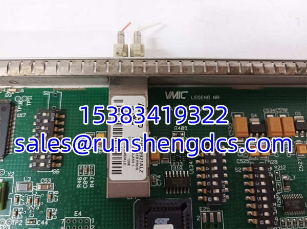
VMIC VMIVME-5565-110000332-015565-110000 P VME-5565
Application Scenarios
Steam/gas turbine control systems (GE Mark series VME‑based racks) use VMIVME‑5565 to synchronize multiple control nodes with deterministic low latency. Power plant full‑scope simulators build multi‑chassis real‑time models; reflective memory shares boiler, turbine and generator state across simulation nodes. Aerospace hardware‑in‑the‑loop (HIL) test benches rely on the hardware mirroring to keep I/O and simulation models tightly synchronized across distributed VME chassis. Military and naval distributed real‑time control platforms deploy these cards where Ethernet non‑determinism cannot meet timing requirements.
Case study: A combined‑cycle simulator had random model desync events every several hours. Technicians first replaced fiber patch cords and couplers. Bench testing revealed degraded transmit optical power on one VMIVME‑5565 transceiver. Replacing the node card eliminated desync; no model software changes required.
FAQ
Q: Does VMIVME‑5565‑110000 support hot‑swap? A: VME backplane may be live‑insertable mechanically, but removing a node breaks the fiber ring unless the network is configured for redundant dual‑fiber topology. Hot‑swap will cause loss of sync across the whole ring in standard single‑ring setups.
Q: What is the difference between -110000 and -111000 variants? A: -110000 = multimode LC fiber (max 300 m). -111000 = single‑mode LC fiber (up to 10 km). They are not optically interchangeable.
Q: Can I mix VMIVME‑5565 with other generations of reflective memory cards on the same ring? A: Generally not recommended. Older RFM generations use different protocol/clocking. Even within 5565 family, FPGA/firmware compatibility must be validated for all nodes.
Q: What lead time applies for tested surplus stock? A: Pre‑burned, multi‑node ring‑tested units ship in 2–5 business days. Units requiring capacitor rework, transceiver replacement and full ring soak test take 10–14 days. No new factory builds exist.
Q: Are refurbished units tested in a multi‑node ring? A: Yes, every unit passes 4+ hours of cross‑node traffic test, CRC validation and optical power measurement. Our report records error counters and optical levels. End‑to‑end validation on your actual system remains mandatory.
Q: What OS are supported? A: Depends on driver availability; commonly VxWorks, QNX, Linux, older Windows real‑time extensions. Drivers are legacy; new OS releases are not supported.
Q: Can this card replace older VMIVME‑5579 or earlier RFM models? A: Form factor is different, protocol and timing differ. Not a direct drop‑in replacement. Requires software/driver changes and full timing validation.