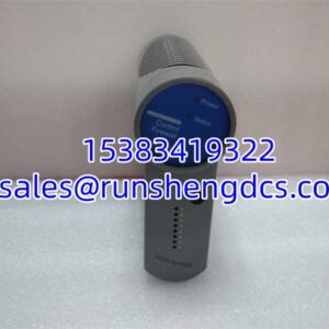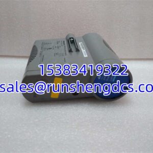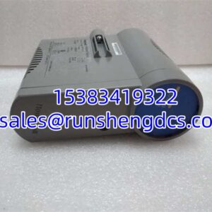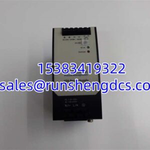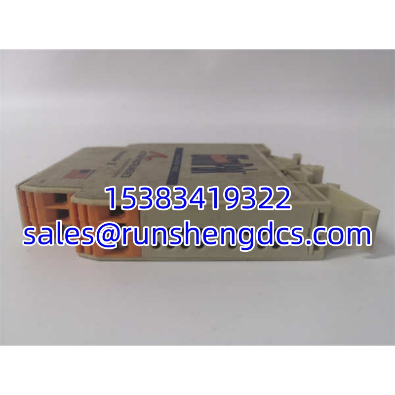

Description
Key Technical Specifications
- Product Model: G448-0002
- Manufacturer: ULTRA SLIMPAK
- Product Type: Signal Conditioner / Isolator
- Mounting Style: DIN Rail
- Primary Function: Signal Isolation and Conditioning
- Input/Output: Analog (Verify specific range on label)
- Isolation: High-Voltage Galvanic Isolation
- Operating Environment: Industrial Control Panel
- Dimensions: Ultra-Slim Profile
- Certifications: CE, UL, CSA (Verify specific model suffix)
Product Introduction
Ground loops are the silent killers of analog accuracy, and the ULTRA SLIMPAK G448-0002 is the shield against them. I’ve walked into panels where 4-20mA signals were drifting 5% just because the sensor ground and PLC ground were at different potentials; this module breaks that path. The G448-0002 takes your noisy, floating field signal and delivers a clean, isolated replica to the controller. It’s not flashy, but when your pH reading stops jumping around every time a pump starts, you’ll appreciate it.
Engineers grab the G448-0002 because it actually fits in tight marshalling cabinets without turning the panel into a convection oven. The “Ultra Slim” name isn’t marketing fluff; these are genuinely thin, allowing you to pack more I/O into standard DIN rail space. One subjective note: check the terminal torque. I’ve seen these loosen up over years of thermal cycling in unheated buildings, leading to intermittent faults that drive techs crazy. A quick retorque during PMs saves hours of troubleshooting later.
Quality SOP & Tech Pitfalls
We don’t guess on signal conditioners. Every ULTRA SLIMPAK G448-0002 gets a visual check for cracked housings or corroded terminals before it hits the bench. Then we run a live signal test: inject a known 4-20mA, measure the output, and verify isolation resistance with a megger. I use a Fluke 115 to confirm the output tracks the input within spec. Firmware or revision codes are logged, and it’s sealed in anti-static wrap.
Here’s the trap: Input Range Mismatches. The G448-0002 comes in dozens of variants (voltage, current, thermocouple, RTD). I’ve seen a tech spend four hours debugging a “bad” module, only to realize he ordered a 0-10V unit for a 4-20mA loop. Always, always verify the suffix and the printed range on the side label. Also, don’t ignore the ground screw. If the has a shield ground terminal, use it. Leaving it floating defeats half the purpose of buying an isolator.
Installation & Configuration Guide
- Pre-Installation: ⚠️ SAFETY FIRST. De-energize the 24V loop power. Photograph the old ‘s wiring and, crucially, the DIP switch settings or jumper positions.
- Removal: Label wires. Release the DIN clip carefully; plastic gets brittle. Pull straight out to avoid bending the rail.
- Installation: COPY DIP/JUMPER SETTINGS NOW. This is the #1 cause of “new module doesn’t work” calls. Align the , press until it clicks, and reconnect wires exactly as photographed. Torque terminals to 0.5 Nm (check manual).
- Power-On & Testing: Restore 24V. Check the status LED (usually green for power, yellow for signal). Inject a test signal or verify the process value in the PLC. Check for ground loop noise; if it’s gone, the is doing its job.
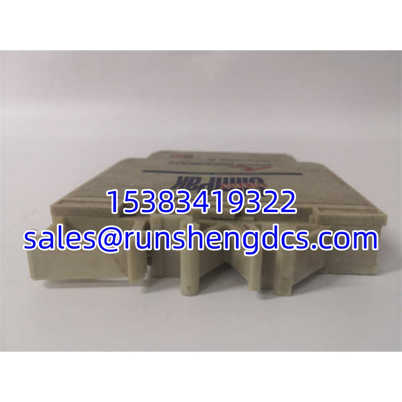
ULTRA SLIMPAKG448-0002
Compatible Replacement Models
- ✅ Drop-in Replacement: (Verify the suffix; ULTRA SLIMPAK changes internal circuits without changing the base model).
- ⚠️ Software Compatible: -RevB (Same footprint, but requires DIP switch verification; expect 10 minutes of config check).
- ❌ Hardware Mod Required: G408-0001 (Different pinout and function; do not force this into a slot unless you are rewiring the entire terminal block).
Frequently Asked Questions
Can I hot-swap this while the loop is live?
Technically, yes, but I don’t recommend it. Pulling the breaks the 4-20mA loop, which will cause the PLC to see an open wire fault. If you’re in a critical process, put the loop in manual or bypass the alarm first. It takes 30 seconds to isolate the loop safely; don’t risk a spurious trip.
The output is stuck at 22mA. Is it broken?
Probably not. That’s usually the ‘s built-in over-range or fault indication. Check your input signal; if it’s open or shorted, the module drives high (or low, depending on config) to tell the PLC something is wrong. Verify your field wiring before condemning the .
Do I need to calibrate this?
No. The is factory-calibrated and sealed. There are no internal pots. If it’s out of spec, replace it. Trying to “adjust” these usually just breaks the calibration seal and voids the safety rating.
Is this suitable for high-noise environments?
Yes, that’s its main job. The provides galvanic isolation that blocks common-mode noise from VFDs and motor starters. Just make sure you’re using shielded cable and grounding the shield at the end, not both ends.
What if I lose the DIP switch chart?
Don’t guess. Look up the datasheet online or check the label on the side. Setting the wrong range via DIP switches can damage the module or give you wildly inaccurate readings. I’ve seen 0-10V signals fed into a mV input because someone guessed; the module smoked instantly.
Does this come with a warranty?
Yes, every we ship has a 1-Year Warranty. We test these because signal conditioners are often the first line of defense against bad data. If it fails, we replace it. No arguments.