
Description
Product Introduction
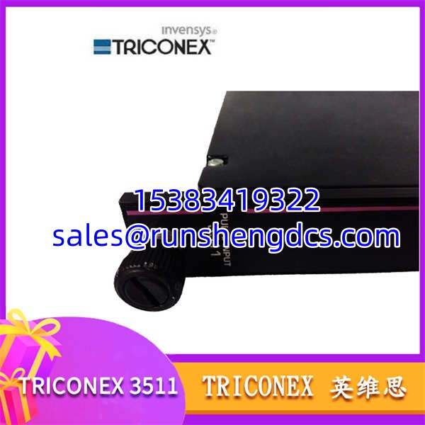
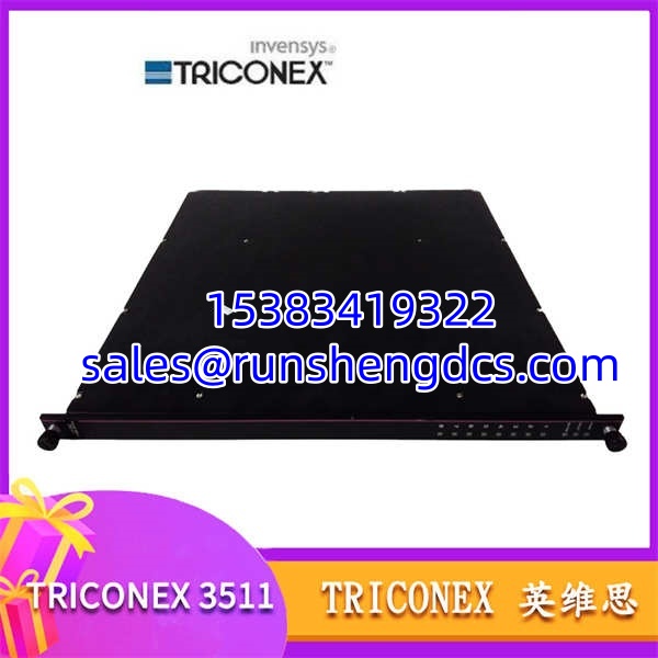
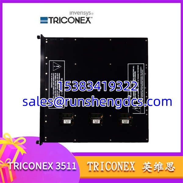
A single bad temperature reading in a high-pressure reactor isn’t a data glitch; it’s a potential runaway reaction. The Triconex 3511 is the analog input module built to be the final word on process conditions in your most critical safety loops. It doesn’t just take a measurement; it validates it through triple-modular redundancy (TMR), ensuring the logic solver acts on truth, not a sensor fault.
This module is the workhorse for analog data in a Tricon system. It handles 16 channels of isolated inputs, which is a crucial detail. That isolation means a ground loop on channel 3 won’t corrupt the reading on channel 4, a common failure mode in less robust designs. In my experience, this channel-to-channel isolation is what separates a reliable safety system from a nuisance-trip generator.
Key Technical Specifications
| Parameter | Value |
|---|---|
| Product Type | Analog Input Module |
| Series Compatibility | Tricon v9, v10, v10.3, v10.6, v11 |
| Channels | 16, Isolated |
| Input Signal Range | 0-20mA, 4-20mA, 1-5V (Software Configurable) |
| Resolution | 16-bit |
| Architecture | Triple-Modular Redundant (TMR) |
| Field Power | 24 Vdc Nominal (from field terminal board) |
| Backplane Power | 5 Vdc, 24 Vdc (from Tricon chassis) |
| In-Channel Isolation | 500 Vdc |
| Diagnostic Coverage | >99% |
| MTBF | >150,000 hours (per SN 29500) |
| Operating Temperature | 0 to 60 °C |
Compatibility & Replacement Matrix
- Triconex 3511 → Triconex 3511E : Needs Adaptation — The 3511E is an enhanced version with different firmware and potentially different terminal board requirements. Do not assume a direct swap. Verify compatibility with your Tricon system’s firmware version.
- Triconex 3511 → Triconex 3501 : Incompatible — The 3501 is a non-isolated analog input module. The wiring and terminal boards are different. Swapping them requires a complete rewiring of the field signals.
- Triconex 3511 → Triconex 3511 (Rev 3.x) : Direct — Revisions within the 3511 model are generally backward compatible, but it’s always best practice to check the firmware requirements for your specific Tricon system version.
Quality Inspection & SOP Transparency
We treat these modules as safety components, not just I/O cards.
- Incoming Inspection: We verify source traceability with the OEM packing list. Every unit gets a physical inspection for damage to the connector pins, PCB traces, and the Triconex label. We check the serial number for authenticity.
- Live Functional Test: We install the module in a live Tricon v10.6 rack. We verify the module is recognized by the TriStation software and comes online without errors. We then simulate a 4-20mA signal on all 16 channels and verify the raw counts in the logic solver match the input within the 16-bit resolution.
- Electrical Parameter Test: We perform a hi-pot test on the field-side terminals to verify the 500 Vdc channel-to-channel isolation. We also check the backplane power draw to ensure it’s within the specified range for a 5 Vdc and 24 Vdc draw.
- Firmware Verification: We read the module’s firmware version and compare it against the compatibility matrix for the Tricon system it was tested in. We document the revision level.
- Final QC & Packaging: After a QC sign-off, the module is sealed in an anti-static bag, packed with foam protectors, and placed in a carton with a “QC Passed” label dated for that day.
TRICONEX 3511
Common Replacement Pitfalls
I’ve seen these mistakes bring down a safety system during a planned outage. Don’t let it happen to you.
- ❗ Firmware Mismatch: This is the big one. A new 3511 module might ship with a newer firmware version than your Tricon processor. The system will fault the module. You must use TriStation to downgrade the module’s firmware to match your system’s expected version.
- ❗ Ignoring the Terminal Board: The 3511 requires a specific field terminal board (like the 3604E or 3607E). You can’t just plug it into a terminal board designed for a 3501 or 3700 series module. The pinouts are different.
- ❗ Forgetting the Module Address: While the 3511 is software-configured, the physical slot address in the chassis is critical. If you pull a module from slot 4 and put the new one in slot 5, your logic is now reading the wrong transmitter. Double-check the slot number.
- ❗ Power Budget Shortfall: Each 3511 draws power from the chassis backplane. If you’re filling an empty chassis, you need to calculate the total power draw of all modules to ensure your power supplies (3601E/3602E) are sufficient.
- ❗ ESD Damage: These are sensitive electronics. Always use a grounded wrist strap. I watched a contractor once install a $5,000 module without one. It never came online.
FAQ
Can I just swap a Triconex 3511 in directly?
Physically, yes. Logically, maybe not. It will plug into the slot, but if its firmware revision doesn’t match what your Tricon processor expects, the module will show up as a fault. You’ll need a laptop with TriStation software to connect to the module and likely perform a firmware downgrade.
My system is Tricon v10.3. Is the 3511 compatible?
Yes. The 3511 is fully compatible with Tricon systems from v9 all the way through to v11. However, you should verify the specific firmware revision on the module itself. A module manufactured recently might have a newer firmware that requires you to update your entire Tricon system, which is a much bigger job.
What’s the difference between the 3511 and the 3501?
The key difference is isolation. The 3511 provides isolated inputs for each channel, meaning a ground fault on one won’t affect the others. The 3501 is non-isolated. They also use different terminal boards and have different power requirements. They are not interchangeable without rewiring.
Does this module come with a terminal board?
No. The 3511 is just the module that plugs into the Tricon chassis backplane. The field terminal board (FTB), which provides the screw terminals for your field wiring, is a separate part number (e.g., 3604E, 3607E) and must be ordered separately.
What is the input impedance for the voltage range?
For the 1-5V input range, the input impedance is typically 1 MΩ. For the current ranges (0-20mA, 4-20mA), the input impedance is 50 Ω. Always verify this against the official Triconex 3511 datasheet for your specific project’s engineering requirements.