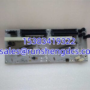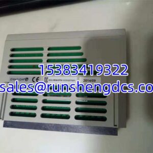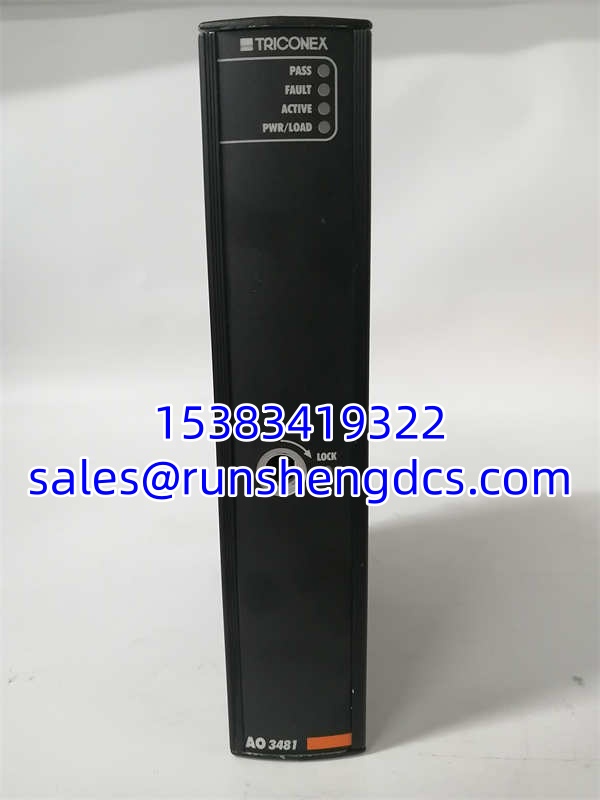

Description
Key Technical Specifications
- Channel count: 4 analog output points
- Signal range: 4–20 mA, overrange to 22 mA
- Resolution: 12 bits
- Typical accuracy: <0.25% FSR across 0–70 °C
- Architecture: Triple Modular Redundant, per‑channel 2oo3 voting
- Loop supply: External 24 VDC nominal; max continuous withstand 36 VDC
- Maximum load: 700 Ω at 20 mA
- Operating temperature: −40 °C to +70 °C
- Storage temperature: −40 °C to +85 °C
- Humidity: 5–95% non‑condensing
- Backplane bus: Tricon proprietary TriBus
- Safety compliance: IEC 61508 SIL 3
- Typical MTBF: 292,000 hours at 40 °C ambient
- Weight: 1.52 kg
Product Introduction
Process safety crews know this failure mode all too well. A drifting AO channel shifts a safety valve position, forcing operators into manual control while they hunt for spare hardware. No new factory builds exist, and full migration requires coordinated outages months out. This TMR analog output module receives digital setpoints from Tricon main processors, runs three independent signal slices, and produces one voted 4–20 mA output for valve positioners and dampers. It cannot execute safety logic locally; voting syncs across its three slices over the TriBus.
Surplus shelf‑aged hardware often develops calibration shift from dried electrolytic capacitors. Onboard diagnostics flag open loops and shorted outputs before they trigger unplanned trips. Within rated temperature limits, channel settling time stays below 2.2 ms. Bottom line — it works, but always run multi‑point calibration after rack installation.
QA/QC Transparency SOP
- Intake & Origin Verification. Cross‑reference serial number against source documentation. Inspect PCB for bulging capacitors, burn traces, or corroded edge connector gold pins. Photograph labels and component side for traceability. Reject units showing liquid contamination.
- Live Functional Testing (Comms, I/O, Load). Seat module in Tricon test rack with matched processor triplet. Apply backplane power. Step each channel through 4 mA, 12 mA, 20 mA setpoints into calibrated resistive loads. Confirm fault flags activate for simulated short‑circuit and open‑loop faults. Maintain continuous test run for minimum 4 hours.
- Electrical Parameter Tests (Megger, Continuity). De‑energize rack. Run 500 V Megger between field wiring terminals and chassis ground. Insulation resistance must exceed 100 MΩ. Verify each signal path continuity with a Fluke 87V.
- Firmware/Config Verification (Readout & Backup). Read onboard slice firmware over TriBus. Archive binary firmware offline. Flag revisions known to cause voting desync; cross‑check against site’s system firmware matrix.
- Final QC & Anti‑Static Packaging. Recheck LED indicators and connector retention force. Place module inside conductive ESD bag, add foam edge protection, pack in rigid carton. Attach unique test report ID to outer packaging.
Field Engineer Gotchas
- Firmware Rev Mismatch. Risk: Mismatched firmware across the three internal slices breaks voting. Outputs freeze or jump sporadically without high‑priority rack alarms. Solution: All three slices on one 3481 must run identical firmware. One maintenance team swapped a module blind and skipped revision checks; they spent four hours chasing erratic valve stroke.
- Common‑return wiring trap. Risk: All four channels share a single return conductor. Ground noise and cross‑talk spread across every output if return wire resistance creeps up. Solution: Use a dedicated heavy‑gauge return path, never daisy‑chain returns between field devices.
- ESD risk during hot‑swap. Risk: Tricon permits hot replacement, but static discharge can silently damage one slice. The module continues operating on the remaining two slices, hiding a single‑fault condition until a second failure occurs. Solution: Bond grounded wrist strap to rack chassis before touching the module.
- Excessive loop resistance. Risk: Loop resistance above 700 Ω prevents the module from reaching full 20 mA. The valve never hits 100% stroke, and built‑in diagnostics sometimes miss this fault. Solution: Measure total loop resistance before energizing each channel.
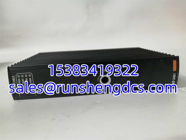
TRICONEX AO3481 3481
Application Scenarios
Refinery hydrocracker pressure control uses voted 4–20mA outputs for pressure‑letdown valves. This AO module delivers SIL3 compliant modulation, isolating safety actions from standard DCS commands. Offshore platform ESD‑linked fuel gas control valves rely on 3481 outputs. TMR voting blocks spurious valve movement triggered by single internal hardware faults. Coal‑fired boiler burner management racks deploy these modules for air‑fuel ratio dampers, where signal drift creates unsafe combustion conditions.
Case study: A 75,000 bpd refinery had one channel drifting upward gradually over 2–4 days. Technicians replaced the valve positioner twice with zero improvement. Bench testing found degraded reference voltage circuitry on one slice. Module replacement eliminated drift; no wiring modifications needed.
FAQ
Q: Does Triconex 3481 (AO3481) support hot‑swap? A: Hot insertion and removal are allowed per Tricon chassis design. Remaining slices maintain output voting during swap. ESD risk remains high; schedule swaps during low‑risk operating windows.
Q: My Tricon system runs Tricon V10.0. Will this drop in? A: Compatibility depends entirely on the module’s slice firmware. Some older 3481 firmware builds fail to sync with V10.0 hosts. Request firmware revision before purchase. Verify with OEM datasheet before installation.
Q: Are individual channels galvanically isolated from each other? A: No. This is a common‑return, DC‑coupled design. All four outputs share a single return path. Do not mix loops fed from separate isolated power supplies.
Q: What lead time applies for tested surplus stock? A: Pre‑calibrated, burn‑in tested units ship 2–5 business days. Units needing capacitor rework and full recalibration take 10–14 days. No new factory production exists.
Q: Do refurbished units ship with calibration certificates? A: Every unit completes multi‑point 4–20mA calibration during QC, and a test record ships with each module. Site functional safety testing remains mandatory per plant SIS procedures.
Q: Can AO3481 be used as a digital output module? A: No. It is analog‑only. It cannot switch discrete digital field circuits.
Q: What happens if one internal slice fails? A: The remaining two slices continue voting, and the module logs a fault. The system stays within SIL3 constraints, but replacement must be scheduled before a second fault occurs.