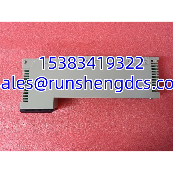
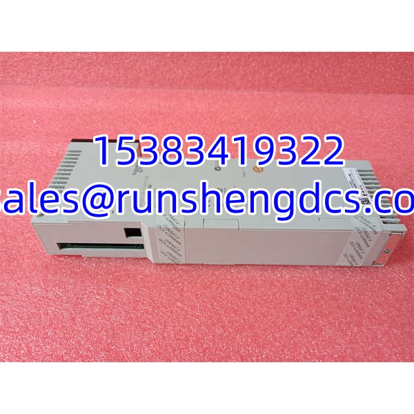

Description
Key Technical Specifications
| Parameter | Value / Notes |
|---|---|
| Product Model | 140DDI35300 |
| Brand | Schneider Electric / Modicon |
| Product Family | Modicon Quantum |
| Module Type | Low-voltage DC discrete input module |
| Discrete Inputs | 32 points |
| Channel Grouping | 4 groups of 8 |
| Logic Type | Positive / sink |
| Nominal Input Voltage | 24V DC |
| Input Voltage Range | 19.2–30V DC |
| State 1 Voltage | 15–30V DC guaranteed |
| State 0 Voltage | -3 to 5V DC guaranteed |
| Input Impedance | 2500 Ω |
| Response Time | ≤1 ms (0→1 and 1→0) |
| Bus Current Requirement | 330 mA |
| Addressing | 2 input words |
| Power Dissipation | 1.7 W + (0.36 × number of ON points) |
| Isolation | Group-to-bus: 1780 Vrms for 1 minute; group-to-group: 500 Vrms for 1 minute |
| Local Indication | 32 green input-status LEDs, 1 red external-fault LED, 1 green bus-active LED |
| Weight | Approx. 0.3 kg |
Product Introduction
Field wiring mistakes on a 32-point DC input card usually show up fast — stuck bits, ghost inputs, or a whole group reading dead because someone tied the wrong common. The Schneider 140DDI35300 is a Modicon Quantum 32-point, 24V DC discrete input module, arranged as 4 isolated groups of 8 channels. It is not an output card, not an analog card, and not a high-voltage AC input module.
In a Quantum system, this module is a standard workhorse for reading proximity switches, limit switches, relay contacts, safety interlock status, and other dry/sink-compatible 24V DC signals. With ≤1 ms response time, 2 input words of addressing, and 330 mA of backplane draw, it fits typical machine-status and process-monitoring duties. The real value is the group isolation: a fault on one 8-point group does not automatically drag the other groups down, assuming wiring and commons are correct.
QA/QC Transparency SOP
- Intake & Origin Verification
Confirm the full part number 140DDI35300. Record the nameplate, hardware revision, date code, serial number, and country markings. Inspect the backplane connector for bent pins, check the front panel for cracked LEDs, and look for corrosion, burnt traces, or moisture damage around the terminal area. - Live Functional Testing
Install in a known-good Quantum-compatible test rack. Verify the module is recognized by the CPU, the green bus-active LED behaves normally, and the red external-fault LED is not latched. Force individual input points with a calibrated 24V DC source and confirm each channel changes state in the PLC I/O map. - Electrical Parameter Tests
Measure bus current draw and confirm it is in the expected range for a 330 mA module. Check input impedance and leakage behavior where test equipment and OEM limits allow. Do not apply voltage above the rated input range during bench testing. - Firmware/Config Verification
Read the module identity, revision, and any diagnostic status visible in the Quantum programming software. Compare it against the target project configuration. A physically correct 140DDI35300 can still cause I/O mapping or diagnostic problems if the project expects a different revision or module type. - Final QC & Anti-Static Packaging
Clean the module, cap open terminals if applicable, and pack in ESD-safe material. Include a test note with power-up status, LED condition, input-point test results, revision data, and photos of the nameplate and front panel.
Field Engineer Gotchas
Sink logic confusion
Risk: The module is wired as if it expects source-type signals, so inputs never turn on.
Fix: The 140DDI35300 is a sink / positive-logic input module. Confirm that field devices switch the positive side correctly and that the module commons are tied to the right 0V reference.
Bottom line — if every point reads OFF but you can measure 24V at the terminal, check sink/source before blaming the card.
Group common wiring errors
Risk: One 8-point group works, the other three do not.
Fix: Each group has its own common reference. Verify group commons, isolation boundaries, and whether the field side is sharing a common with other cards or power supplies.
War story: A technician swapped a “bad” 140DDI35300 twice before noticing the panel had one 0V bus tied to group A and a separate 0V tied to groups B–D. The module was fine; the wiring was lying.
Overvoltage and transient damage
Risk: A 24V field circuit gets hit with a higher voltage spike, and the input group fails.
Fix: Respect the 30V continuous absolute maximum and the 56V / 1.3 ms decaying pulse limit. Use snubbers, transient suppression, or isolation relays on inductive loads.
Blunt warning: This module has input protection, but it is not a license to abuse field wiring.
Backplane power budget
Risk: The Quantum rack is already loaded, and the new DI module causes marginal bus-current behavior.
Fix: Add the 330 mA requirement to the chassis power budget before installation.
Do not assume a small DI card is “free” from a power standpoint.
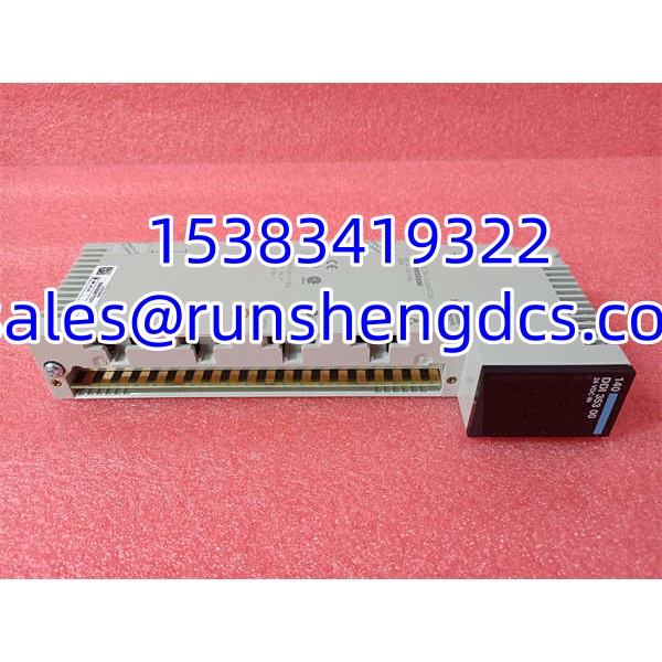
Schneider 140DDI35300
Application Scenarios
- Machine safety and status monitoring
Reads limit switches, E-stop auxiliary contacts, guard-door interlocks, and permissive signals where group isolation helps separate safety-related status from general machine status. - Conveyor and material-handling systems
Used for photoeye, proximity, and position-feedback signals on belts, diverters, and accumulation zones in packaging or distribution automation. - Water/wastewater pump stations
Monitors pump run status, float switches, pressure switches, and valve feedback across distributed Quantum I/O racks. - Power plant auxiliary systems
Reads contact closures from relays, motor starters, and auxiliary panels where 24V DC control circuits feed back into the PLC. - Legacy Modicon Quantum plant maintenance
Used as a direct replacement for failed Quantum DI cards when the installed base still depends on 140DDI35300 modules and a full I/O migration is not planned.
Case study — anonymized
A packaging line kept tripping a fault because one 140DDI35300 input group showed all points ON at the same time, even though only one sensor was active. Maintenance replaced the module. The replacement did the same thing. The real problem was a shorted 24V wire in a junction box that back-fed the entire group common. Once the short was found and the damaged cable was replaced, the module read correctly. Lesson: when a whole group misbehaves together, look at the field wiring and common before condemning the card.
FAQ
Is the 140DDI35300 an input or output module?
Input only. It is a 32-point 24V DC discrete input module, not an output card.
How many inputs does it have?
It has 32 discrete inputs, organized as 4 groups of 8.
What voltage does it accept?
It is a 24V DC module with an operating input range of 19.2–30V DC. Do not treat it as a 120V AC or 10–60V DC module.
Is it sink or source?
It is a sink / positive-logic input module. Field devices typically switch the positive side, and the module commons must be referenced correctly.
How much backplane current does it draw?
Approximately 330 mA. That must be included in the Quantum chassis power budget.
How much power does it dissipate?
Typical power dissipation is 1.7 W + (0.36 × number of ON points). If all 32 points are ON, calculate accordingly before evaluating cabinet heat load.
Will any 140DDI35300 drop into my Quantum rack?
Not automatically. The part number must match, but you should also verify hardware revision, firmware/project configuration, slot assignment, and field-wiring polarity before installation.