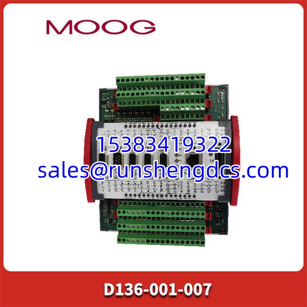
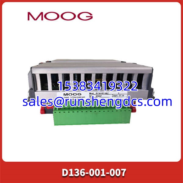

Description
Product Introduction
When controlling high-pressure hydraulic servo actuators, a millisecond of lag or signal noise can mean the difference between precision and catastrophic mechanical failure. The MOOG D136-001-007 is the MSC I series servo controller engineered specifically to solve this challenge, delivering fast, accurate closed-loop control for up to two hydraulic axes. It is not merely an amplifier; it is a fully integrated motion controller with a built-in PLC, designed to coordinate complex machine processes directly at the drive level.
In our field experience, the MOOG D136-001-007 stands out because of its deterministic processing. Built on a PowerPC architecture with 4MB of RAM and Flash memory, it executes MACS (Moog Axis Control Software) with cycle times as fast as 400μs. Whether you are retrofitting an aging test rig or commissioning a new industrial forming press, the MOOG D136-001-007 provides the modular, tool-free DIN rail mounting and robust I/O (8 analog inputs, 8 digital I/O) needed to keep your most critical motion applications running flawlessly.
Key Technical Specifications
- Product Model: D136-001-007
- Manufacturer: MOOG
- Product Type: MSC I Servo Controller / Motion Controller
- Processor: PowerPC based
- Memory: 4 MB RAM / 4 MB Flash EEPROM
- Control Axes: Up to 2 hydraulic servo actuators (Closed-Loop)
- Cycle Time: From 400 μs
- Power Supply: 24 VDC
- I/O Capacity: 8 Analog Inputs, 2 Analog Outputs, 8 Digital I/O, 2 Position Sensors
- Communication: Ethernet (1), CAN/CANopen (2), Profibus DP (Optional)
- Protection: Overvoltage protection up to ±36V, IP20
Application Scenarios & Pain Points
The MOOG D136-001-007 typically becomes the focal point when a plant needs to replace a failing legacy controller or upgrade a system requiring tighter synchronization between hydraulic actuators. We’ve seen cases where an aging controller’s drift caused uneven force distribution in a multi-actuator press, leading to premature seal wear. This module acts as the precision brain, utilizing MACS software to continuously adjust position, speed, and force parameters in real-time.
- Material Testing & Simulation: Used in aerospace and automotive test rigs to simulate extreme aerodynamic or road loads. The MOOG D136-001-007’s 400μs cycle time ensures that the hydraulic actuators perfectly replicate the commanded waveforms without phase lag.
- Steel & Metal Forming: Controlling the precise stroke and force of hydraulic presses. The integrated PLC functionality allows the to handle local machine logic and safety interlocks directly, reducing the load on the main plant DCS.
- Plastics Injection Molding: Managing high-pressure clamp and injection axes. The module’s robust analog I/O and wire-fault monitoring ensure that sensor feedback remains reliable even in electrically noisy factory environments.
- Wind Turbine Pitch Control: Adjusting blade angles in high winds. The ’s ability to operate across a wide temperature range (-25°C to +70°C) and its CANopen connectivity make it ideal for remote, harsh-weather nacelle installations.
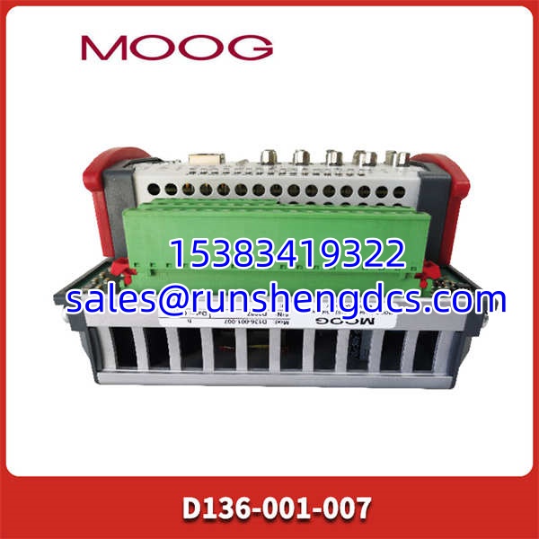
MOOG D136-001-007
Quality Control Process
We know that a servo controller with a degraded capacitor can introduce fatal oscillation into a hydraulic system. That’s why our QC for the goes far beyond a visual check. We treat every unit as a critical safety and performance component, and our testing reflects that level of scrutiny.
- Visual & Mechanical Inspection: We inspect the for damaged DIN rail clips, bent D-Sub/CAN connectors, and verify the integrity of the terminal blocks. We also check for any signs of thermal stress on the internal PowerPC and power regulation components.
- Power & Protection Verification: We apply 24VDC and verify the internal power rails. We then simulate an overvoltage condition (up to ±36V) on the analog I/O lines to confirm that the internal protection circuits clamp the voltage correctly without damaging the ADCs.
- MACS Software & Logic Test: Using Moog Axis Control Software, we establish communication via Ethernet/CAN. We configure a basic 2-axis closed-loop test, verifying that the processor can execute the 400μs cycle time and that the integrated PLC logic executes without watchdog timeouts.
- Signal Integrity Check: We inject calibrated analog signals into all 8 inputs and verify the digital readout in MACS matches our reference standard. We also verify that the digital I/O and wire-fault monitoring LEDs trigger accurately.
- Final Certification: Only units passing all electrical, communication, and logic tests receive our QC label. We provide a test report detailing the cycle times and I/O accuracy for your maintenance records.
Installation Pitfalls Guide
I’ve seen a perfectly good fail to control an actuator because of a missed ground or a misconfigured CAN termination. Don’t let a simple wiring error cost you days of commissioning time. Here are the traps we see most often:
- CAN Bus Termination: The uses a QEBUS-CAN module with D-Sub connectors. Verify the CAN termination resistors. The module provides jumpers to connect/disconnect the 120Ω termination resistors. If you are at the end of the bus and forget to close the jumper, you will get intermittent communication errors.
- Zero Voltage Protection: This controller has strict undervoltage and zero-voltage protection. If your 24VDC supply sags during actuator startup inrush, the will safely trip and require a manual restart. Ensure your power supply is adequately sized for the peak hydraulic load.
- Sensor Wiring Faults: The module features active wire-fault monitoring for all digital sensor inputs. If you are getting persistent fault LEDs, check your sensor shielding. Running sensor cables parallel to high-voltage hydraulic pump motors without proper shielding will induce noise that the controller interprets as a broken wire.
- MACS Parameterization: Do not assume factory defaults will work for your hydraulic valves. The hardware functionality must be parameterized via MACS software before operation. Incorrect gain tuning on the can cause hydraulic hunting or actuator runaway.
- Heat Dissipation: While it operates up to 70°C, the generates heat during continuous high-load processing. Ensure adequate clearance around the DIN rail module and verify that your control cabinet cooling fans are functioning properly.