
Description
Key Technical Specifications
| Parameter | Typical / Verified Detail |
|---|---|
| Part Number | VMIVME-2128 |
| Manufacturer | GE Fanuc / VMIC (legacy); later Abaco Systems |
| Product Type | VMEbus digital output module |
| Bus Interface | VMEbus, P2 connector |
| Channel Count | 128 digital outputs |
| Output Type | Open-collector, current-sink |
| Output Voltage Range | 5 to 48 VDC |
| Max Sink Current | 600 mA per channel (aggregate limits apply) |
| Breakdown Voltage | 55 V |
| Board Power | +5 VDC ±5% from VME backplane |
| Diagnostics | Built-in test (BIT) for per-channel verification |
| Protection | Surge-current shutdown, overheat protection |
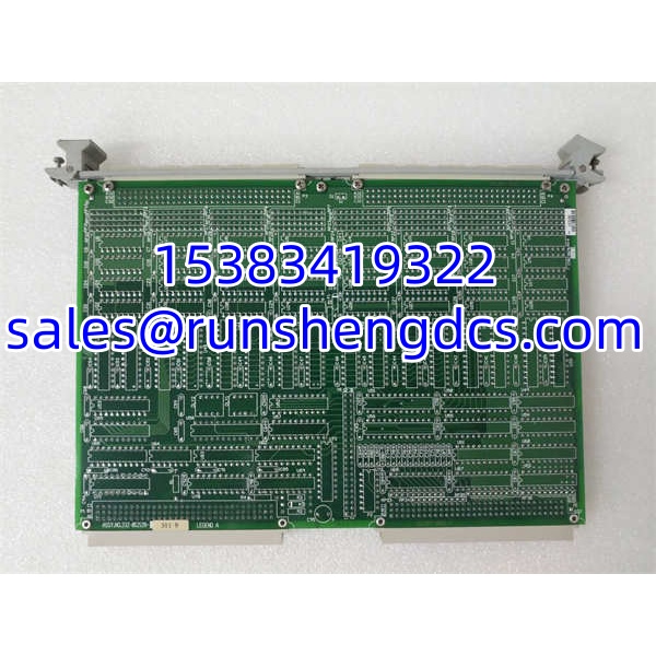
| Mechanical | 3U VME form factor; some VMIC variants offered in 6U |
| Operating Temp | Reported ranges vary by source (0 °C to 70 °C or -40 °C to +85 °C); confirm nameplate |
Product Introduction
High-density DO boards do not fail gracefully. A single shorted field wire on a 128-channel output card can pull down an entire bank, mask a safety interlock or force a VME crate reboot at the worst possible moment. The VMIVME-2128 is the kind of module you want verified under load before it ever reaches the rack.
The GE VMIVME-2128 is a 128-channel digital output module for VMEbus systems, built around open-collector sink drivers rated for 5 to 48 VDC operation. It is commonly found in legacy test rigs, semiconductor equipment, aerospace ground-support systems and industrial automation platforms where GE Fanuc/VMIC VME crates were deployed. The board draws +5 VDC from the backplane, provides per-channel sink capability up to 600 mA, and includes built-in test logic so operators can verify output states without external stimulus.
Bottom line: this is a high-density spare for existing VMIC/VME installations. It is not a modern PLC remote I/O module, and it should not be treated as a generic “128-point DO card” without confirming voltage, current, VME slot compatibility and driver support.
QA/QC Transparency SOP
- Intake & Origin Verification — Confirm VMIVME-2128 labeling, board revision, serial number and physical condition. Reject units with burnt driver ICs, damaged P2 connectors, corrosion or missing front-panel hardware.
- Visual & Mechanical Inspection — Inspect all output terminal blocks or ribbon connectors, P2 pins, fuse/protector components and heatsinking on driver stages. Check for rework, lifted traces or replaced components.
- Electrical Parameter Tests — Power the board from a controlled VME backplane or test fixture. Verify +5 VDC rail integrity. Test a representative sample of channels for open-collector switching, leakage and breakdown behavior. Check for shorted outputs.
- Functional & BIT Verification — Run built-in test routines to confirm per-channel diagnostics. Validate that output states can be set and read back through the VME interface. Confirm driver/software compatibility with the target VME CPU.
- Final QC & Packaging — Seal in ESD-safe, anti-static packaging with photos, revision number, test log and a packing list noting which channels were tested and which require on-site validation.
Field Engineer Gotchas
- It is DO-only, not mixed I/O. Do not assume analog input, digital input or fieldbus capability. Some online listings incorrectly describe it as a general-purpose I/O or Modbus module.
- 600 mA per channel is a maximum, not a design target. Continuous operation near 600 mA will stress driver stages and thermal protection. Derate for ambient temperature and channel grouping.
- Inductive loads need external flyback protection. Relays, solenoids and valve coils without proper snubbing can destroy open-collector outputs. The board’s surge protection is not a substitute for proper field-side clamping.
- VME driver support is legacy. Windows 10/11 or modern Linux kernels may not have ready-made drivers. Confirm driver availability for your VME CPU OS before committing to a replacement.
- Aggregate current limits matter. Even if each channel is rated 600 mA, the board’s total sink capacity is limited by backplane power, connector ratings and internal traces. Check the official datasheet for bank/group current limits.
- Temperature rating varies by source. Published operating ranges conflict between listings. Treat the installed nameplate and OEM datasheet as authoritative.
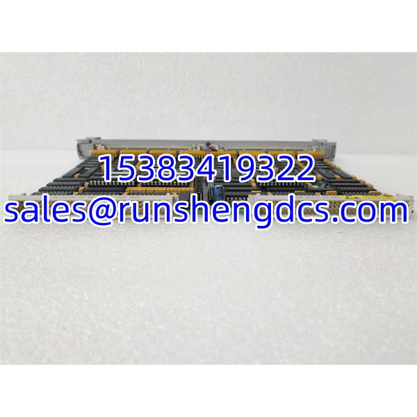
GE VMIVME-2128
Application Scenarios
- Legacy VME test equipment. Drives relay matrices, indicator lamps, valve solenoids and actuator enable lines in automated test systems.
- Aerospace ground-support systems. Controls pneumatic valves, hydraulic test fixtures and safety interlocks where VMIC VME crates were historically deployed.
- Semiconductor and electronics manufacturing. Provides high-density discrete outputs for handler control, fixture actuation and process sequencing.
- Industrial automation retrofits. Serves as a like-for-like replacement in aging GE Fanuc/VMIC VME systems where migration to a new platform is not yet feasible.
FAQ
No. The VMIC product line is legacy. GE Fanuc’s industrial business was later absorbed, and Abaco Systems supported portions of the VMIC/VME portfolio. Availability today is primarily surplus, refurbished or used.
Can I use it as a digital input board?
No. The is a digital output module. Digital input applications require a separate VMIC DI board.
Does it support Modbus, Profibus or Ethernet?
No. It is a VMEbus I/O module that communicates through the VME backplane to a VME CPU. Any Modbus/Profibus/Ethernet connectivity would come from the VME CPU or gateway, not from this board.
What voltage levels does it support?
The outputs are open-collector and support 5 to 48 VDC field circuits, with a 55 V breakdown rating. The board itself runs from +5 VDC on the VME backplane.
Is it compatible with all VME crates?
Mechanically it is a VME P2 module, but electrical compatibility, driver support and slot mapping depend on the VME CPU and backplane. Confirm with your system integrator before installation.
Can I replace it with a modern PLC remote I/O module?
Not directly. A migration would require rewiring, logic changes and possibly a new control architecture. For like-for-like replacement, source a verified or consult Abaco/GE legacy support.
Should I load-test it before installation?
Yes. For 128-channel output boards, always verify a representative sample of channels under actual field voltage and current. Power-on tests alone do not reveal degraded driver stages.