
Description
Key Technical Specifications
| Parameter | Specification |
|---|---|
| Product Model | IS200PMCIH1ABA |
| Manufacturer | GE (General Electric) |
| Product Series | Speedtronic Mark VI / Mark VIe Turbine Control |
| Product Type | Analog I/O Pack (TCQA Board) |
| Core Compatibility | RST Redundant Cores (R1, R2, R3) |
| Signal Types Processed | LVDT input, servo valve output, thermocouple input, 4–20 mA I/O, vibration input, relay driver output, pulse input, voltage input, generator & line signals |
| Analog Output Current Range | 0–20 mA (configurable via hardware jumpers J5/J6: 20 mA or 200 mA) |
| Maximum Lead Resistance | 15 Ω |
| Power Supply | 24VDC output (system-supplied) |
| Operating Temperature | -30°C to +65°C |
| Storage Temperature | -40°C to +85°C |
| Conformal Coating | Yes — chemical protective coating for moisture, dust, and corrosion resistance |
| Hardware Jumpers | J1/J2 (mA output circuit selection), J5/J6 (mA output range: 20 mA or 200 mA), J7 (RS232 card test port), J8 (oscillator start) |
| Connectors | 3PL (data bus to STCA/TCQA/TCQE boards), JE (generator/line signals to TCQC board), JF (LVDT/LVDR position input from TBQC), JG (±10 VDC + vibration input from TBQB), JD (trip signal to TCTG board) |
| Mounting | VME backplane slot in Mark VI/VIe I/O core rack |
| Certifications | CE (EMC Directive 89/336/EEC, Low Voltage Directive 73/23/EEC), EN 50081-2, EN 50082-2, EN 61131-2 |
| Product Status | Legacy / Discontinued — spare/replacement only |
Product Introduction
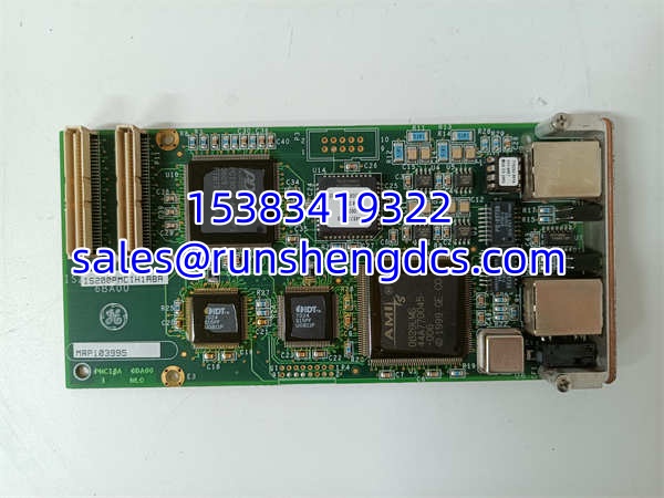
When a GE Speedtronic turbine control system needs to translate real-world analog signals into data the RST cores can act on, the IS200PMCIH1ABA is the board that does the heavy lifting. This isn’t a generic analog input card — it’s a purpose-built TCQA (Terminal Card for Quadrature Analog) I/O pack designed specifically for GE’s Mark VI and Mark VIe turbine control architectures, handling the critical signal conditioning that sits between field sensors and the redundant controller cores.
The IS200PMCIH1ABA processes a wide range of analog signals that are essential for turbine operation: LVDT position feedback from fuel valves and actuator servos, 4–20 mA process signals (compressor stall detection, fuel flow pressure, lube oil pressure), thermocouple inputs for exhaust temperature monitoring, vibration signals from proximity probes, pulse inputs from speed pickups, and generator/line voltage and current signals. Each signal type is scaled, filtered, and conditioned before being passed to the R, S, and T cores via the 3PL data bus connector — ensuring that the control algorithms are working with clean, accurate data.
The board is conformal coated, meaning a thin chemical protective layer covers the PCB surface. This is critical for turbine control applications where the I/O racks may be exposed to humidity, salt air (offshore platforms, marine installations), or chemical contaminants. The coating prevents moisture ingress, dust accumulation, and corrosion on solder joints and component leads — a common failure mode in uncoated boards operating in harsh environments.
Hardware configuration is done via jumpers rather than software, which is both a strength and a consideration. J1 and J2 select the milliamp output circuit, J5 and J6 set the mA output current range (20 mA or 200 mA), J7 provides an RS232 test port for card diagnostics, and J8 starts the oscillator. This jumper-based approach means configuration is fixed and deterministic — no firmware bugs can change your mA range — but it also means you need to physically access the board and verify jumper positions during commissioning or replacement.
The IS200PMCIH1ABA interfaces with several other boards in the Mark VI/VIe ecosystem: it sends conditioned signals to the STCA board via the 3PL connector, communicates generator and line signals with the TCQC board via the JE connector, receives LVDT/LVDR position inputs from the TBQC terminal board via JF, and accepts ±10 VDC and vibration inputs from the TBQB terminal board via JG. It’s part of a tightly integrated signal chain, not a standalone device.
Why it matters: in a turbine control system, the analog I/O pack is the front line of data integrity. If the IS200PMCIH1ABA misreads a fuel valve LVDT position or a compressor stall pressure signal, the control cores make decisions based on bad data — which can lead to poor combustion, overspeed events, or unnecessary trips. Having a tested spare on the shelf means you can swap out a failing board during a planned outage rather than scrambling for an obsolete part after an unplanned trip.
QA/QC Transparency SOP
Every IS200PMCIH1ABA goes through a five-step verification process:
- Intake & Origin Verification: We cross-check the module’s part number label (), serial number, and revision code against GE’s known production records for the Mark VI/VIe series. We verify the conformal coating is intact and matches GE’s original application pattern — re-coated or uncoated boards are flagged.
- Visual & Mechanical Inspection: We inspect the PCB for burnt components, cracked solder joints, or corrosion under the conformal coating. We verify that all connector pins (3PL, JE, JF, JG, JD) are straight and undamaged. We check that all hardware jumpers (J1, J2, J5, J6, J7, J8) are present and properly seated.
- Power-Up & Self-Test: We apply 24VDC power and verify that the board powers up correctly. We use the J7 RS232 test port to run the built-in card self-test, checking ADC accuracy, output driver functionality, and oscillator operation. We verify that the J8 oscillator starts and runs at the correct frequency.
- Signal Conditioning Verification: We simulate 4–20 mA inputs and verify the board scales and conditions them correctly within spec. We simulate LVDT inputs and verify position feedback accuracy. We verify the mA output circuit (J1/J2) and output range (J5/J6) are configured correctly per the jumper settings. We check isolation between channels to confirm no cross-talk.
- Final QC & Anti-Static Packaging: After passing all tests, the board is bagged in ESD-safe packaging with a printed test report. No unit ships without a signed-off QC sheet documenting power-up test, self-test results, signal conditioning accuracy, jumper configuration, and visual inspection.
Field Engineer Gotchas
- H1A Revision Boards Are Obsolete: Many boards in the field are H1A revision, which GE has discontinued. H1A boards are prone to component aging failures (capacitor drying, solder joint fatigue) and spare parts are extremely difficult to source. If you’re replacing an H1A board, verify whether your system has been upgraded to a newer core revision (H1B or later) that accepts newer I/O packs. War story: A combined-cycle plant in the Middle East had an H1A fail on Unit 2 during summer peak demand. The board’s 4–20 mA input channel for compressor stall detection went open, causing a false stall alarm and an unnecessary turbine trip. They couldn’t find an H1A replacement anywhere — had to upgrade the entire I/O core to H1B revision, which required a 3-day outage and reconfiguration of the ToolboxST software.
- Jumper Configuration Must Match Original: The is configured via hardware jumpers, not software. If you’re replacing a board, you must replicate the exact jumper configuration (J1, J2, J5, J6) from the original board. A wrong jumper setting on J5/J6 can change the mA output range from 20 mA to 200 mA, causing downstream devices to receive 10× the expected current — potentially damaging valves or actuators. Always photograph the original board’s jumper positions before removal.
- Conformal Coating Can Mask Problems: While the conformal coating protects against environmental damage, it can also hide developing problems. Corrosion under the coating, cold solder joints, or component lead fractures may not be visible during a casual inspection. If a board is exhibiting intermittent signal issues, the problem may be under the coating — requiring careful removal of the coating in the affected area for diagnosis.
- Not Hot-Swappable in All Configurations: While the Mark VIe system supports some level of hot-swap capability, GE’s official guidance is to de-energize the I/O core slot before removing or inserting an I/O pack. Hot-swapping can cause transient signals on the 3PL data bus that may disrupt the RST cores’ communication. Always follow your plant’s specific procedures.
- J7 RS232 Test Port Is Undocumented in Many Manuals: The J7 connector provides RS232 access for card-level diagnostics, but this feature is poorly documented in many versions of the GE Mark VI/VIe technical manuals. If you’re troubleshooting a suspect board, the J7 port can be invaluable for running self-tests and reading internal diagnostics — but you’ll need the correct RS232 cable and terminal settings.
- LVDT Input Wiring Polarity Matters: The LVDT inputs on JF are polarity-sensitive. Reversing the LVDT wiring will cause the position feedback to be inverted — the control cores will think the fuel valve is closing when it’s actually opening, which can cause dangerous overfueling conditions. Always verify LVDT polarity during commissioning.
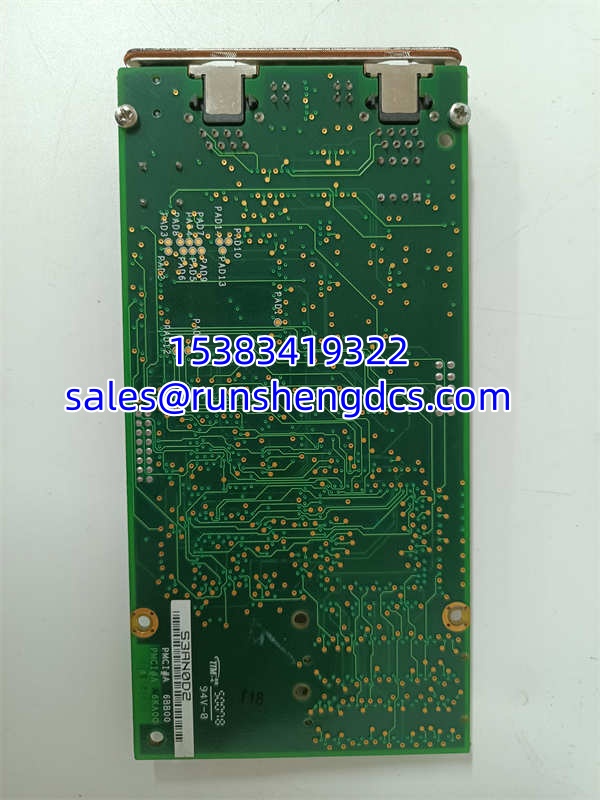
GE IS200PMCIH1ABA
Application Scenarios
- Gas turbine combustion control: Processing LVDT feedback from fuel gas control valves and liquid fuel servo valves, 4–20 mA signals from fuel flow meters and compressor discharge pressure transmitters, and thermocouple inputs from exhaust temperature grids. The conditions these signals for the RST cores to execute combustion control algorithms, maintaining proper fuel-air ratio and preventing lean blowout or rich overtemperature conditions.
- Steam turbine governing: Processing LVDT feedback from main steam control valves and intercept valves, 4–20 mA signals from lube oil pressure and bearing temperature sensors, and speed pickup pulse inputs. The board provides the analog interface for the turbine’s speed and load control loops.
- Generator protection and monitoring: Processing generator terminal voltage and current signals, line voltage signals, and protective relay outputs via the JE connector. The passes these signals to the control cores for synchronization, load sharing, and protective tripping functions.
- Vibration monitoring interface: Accepting vibration signals from proximity probes and accelerometers via the JG connector (±10 VDC input from TBQB terminal board). The board conditions these signals for the control cores to monitor bearing health and trigger alarms or trips on excessive vibration.
- Spare parts for aging Mark VI/VIe installations: Many GE turbine control systems are 15–25 years old. boards can fail due to component aging, conformal coating degradation, or connector wear. Since the product is legacy/discontinued, having a tested spare on the shelf is essential for minimizing unplanned outage time.
FAQ
A: The is primarily a Mark VI/Mark VIe board. Some sources conflate it with Mark V TCQA boards (like IS200PMCIH1AB without the final “A”), but they are not directly interchangeable. Verify your system’s series and core revision before ordering.
A: IS200PMCIH1AAA6BA00 is a variant part number that may represent a specific revision or configuration of the same base board. The core functionality (TCQA analog I/O processing) is the same, but the suffix may indicate different jumper configurations, firmware, or manufacturing batches. Always verify the exact part number on your existing board’s label.
A: No. The is configured via hardware jumpers (J1, J2, J5, J6, J7, J8). There is no software configuration interface for the board itself. The ToolboxST software configures the control cores’ logic, but the board’s analog range and circuit selection are set physically via jumpers.
A: The Mark VIe system has some hot-swap capability, but GE recommends de-energizing the I/O core slot before removing or inserting an I/O pack to avoid transient disruptions on the 3PL data bus. Always follow your plant’s specific procedures and GE’s official guidance.
A: The #1 cause is component aging on H1A revision boards — electrolytic capacitors dry out, solder joints fatigue, and conformal coating degrades over 15–20 years of operation. The second most common issue is connector pin wear from repeated insertion/removal, especially on the 3PL and JE connectors. Intermittent solder joint fractures under the conformal coating are also common and difficult to diagnose visually.
Q: Can I use a non-GE analog I/O card as a replacement?
A: No. The communicates with the RST cores via GE’s proprietary 3PL data bus protocol and interfaces with GE-specific terminal boards (TBQA, TBQB, TBQC, TCQC). A generic analog I/O card will not be compatible with the Mark VI/VIe architecture.