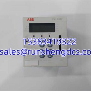


Description
Key Technical Specifications
- Product Type: Genius I/O Terminal Base Assembly
- Circuit Count: 32 Discrete Circuits
- Nominal Voltage: 24 VDC (Operational Range: 18-30 VDC)
- Terminal Type: Screw-Clamp, Field Wiring Interface
- Max Output Current: 0.5 A per circuit / 16 A total module
- Max Surge Current: 4 A for 10 ms
- Input Impedance: 3.3 kΩ
- Power Consumption: 18 W @ 5 A rated current
- Compatible Blocks: IC660BBD025, IC660EBD025
- Dimensions: 224 x 90 x 112 mm (8.8 x 3.5 x 4.4 in)
- Weight: 1.8 kg (4.0 lbs)
- Operating Temp: 0°C to 60°C
Product Introduction
When a Genius I/O block fails, 90% of the time the electronic module is the culprit, not the wiring base. But when the GE IC660TBD025 does need replacement, it’s usually because of corroded screw terminals, cracked plastic from overtightening, or backplane pin damage during a botched hot-swap. This terminal base is the passive backbone of the Genius I/O system, providing the 32-circuit field wiring interface and the critical backplane communication path that lets the electronic block talk to the Genius Bus Interface Module.
The GE IC660TBD025 is mechanically keyed to accept only compatible 24VDC discrete blocks like the IC660BBD025 or IC660EBD025. You cannot force a 115VAC base into this slot, and vice versa. The base itself has no active electronics, but the backplane pins are precision-machined and fragile. I’ve seen more GE IC660TBD025 units fail from bent pins during rushed maintenance windows than from actual electrical failure. Treat the backplane connector like glass, and always verify the terminal torque spec; overtightening strips the threads and guarantees a future field wiring fault.
QA/QC Transparency SOP
- Intake & Origin Verification: We inspect the GE IC660TBD025 for physical cracks, terminal corrosion, and verify the molding date code matches the era of your existing Genius I/O installation.
- Live Functional Testing: A known-good IC660EBD025 electronic block is installed to verify backplane communication, LED indicators, and that the base properly seats and locks onto the DIN rail or panel mount.
- Electrical Parameter Tests: Using a calibrated Fluke multimeter, we perform continuity tests on all 32 field terminals and measure insulation resistance between the field side and backplane to rule out internal shorts or moisture damage.
- Firmware/Config Verification: While passive, we verify the base part number stamping and keying matches the GE IC660TBD025 documentation to ensure it will accept your specific electronic block without mechanical interference.
- Final QC & Anti-Static Packaging: After passing all tests, the GE IC660TBD025 is cleaned, sealed in ESD-safe packaging, and shipped with a test report confirming terminal continuity and backplane pin integrity.
Field Engineer Gotchas
Electronic Block Compatibility: The is a terminal base, not an active module. It must be paired with a compatible electronic block like the IC660BBD025 or IC660EBD025. I’ve seen techs order just the base, install it, and then panic when nothing works because they forgot the electronic block is a separate part number. Always verify you have both components.
Backplane Pin Damage: The backplane connector on the uses fragile spring-loaded pins. If you force the electronic block at an angle, you’ll bend or break them. I’ve seen a $5,000 base ruined because a tech didn’t align the block perfectly before tightening the captive screws. Always seat the block squarely and hand-tighten the screws in a crisscross pattern.
Terminal Torque Specs: The screw terminals on the are rated for a specific torque. Overtightening strips the threads or cracks the terminal block; undertightening causes intermittent connections and arcing. Use a calibrated torque screwdriver. I’ve seen field wires melt at the terminal because a tech used an impact driver to “make sure it was tight.”
Wiring Base vs. Electronic Block Confusion: The is the wiring base only. The active electronics (CPU, diagnostics, switching) are in the IC660EBD025 block that plugs into it. If you’re getting communication faults, the problem is almost always the electronic block, not the base. Don’t replace the base unless you have physical damage or terminal failure.
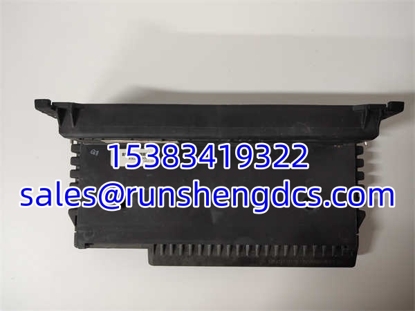
GE IC660TBD025
Application Scenarios
Legacy Manufacturing Lines: Maintaining continuous operation in automotive or packaging plants where the entire control strategy is tied to Genius I/O. The provides the field wiring interface for decades-old discrete I/O, and finding a tested replacement base is cheaper than migrating to PACSystems.
Harsh Environment Installations: In food & beverage or wastewater facilities, the terminals are exposed to washdown and chemical exposure. Corrosion is the #1 failure mode. When terminals turn green or pitted, replace the before you start chasing intermittent sensor faults.
Retrofit & Expansion Projects: When adding I/O to an existing Genius I/O rack, the must be verified for slot availability and backplane power budget. Each base draws power from the bus, and overloading the power supply is a common mistake. Verify your power supply can handle the additional 18W load before installing a new .
Case Study: A bottling plant’s Genius I/O rack started showing intermittent “Field Wiring Fault” alarms on a 24VDC input group. Diagnostics pointed to the terminal base. The had three terminals with stripped threads from years of maintenance abuse. We shipped a tested replacement base. The tech rewired the field connections with proper torque, and the faults disappeared immediately. The old base was retired to the scrap pile.
FAQ
Is the the same as IC660BBD025?
No. The is the passive terminal base (wiring interface). The IC660BBD025 is the active electronic block that plugs into it. You need both to make a functional I/O point. The base provides the screws and backplane; the block provides the brains.
Can I use this base with a 115VAC electronic block?
No. The is mechanically and electrically keyed for 24VDC discrete blocks only. A 115VAC block like the IC660TBD110 will not physically fit, and forcing it will damage the backplane pins. Always match the voltage rating.
Does this base have any active electronics?
No. The is entirely passive. All switching, diagnostics, and communication logic reside in the electronic block (IC660EBD025 or IC660BBD025) that plugs into it. If you’re getting communication errors, the problem is the block, not the base.
What is the max current per terminal?
0.5 A per circuit, with a total module limit of 16 A. Don’t try to pull 2A through a single terminal on the ; you’ll overheat it and melt the plastic. Use external relays or contactors for higher loads.
Can I hot-swap the electronic block on this base?
Yes, but follow proper procedure. Power down the field devices first, then remove the electronic block. The remains powered from the backplane, but the field circuits are de-energized. Never pull the base itself while the backplane is live; that requires a full rack shutdown.
Are these tested or just pulled?
Every we sell is tested for terminal continuity and backplane pin integrity. We don’t sell untested pulls. You’ll receive a unit with a test report confirming the wiring interface is healthy and ready for your electronic block.