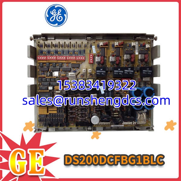

Description
Key Technical Specifications
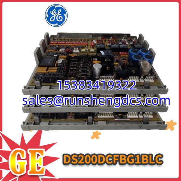
- Product Model: GE DS200DCFBG1BLC
- Manufacturer: General Electric (GE)
- Module Type: DC Power and Feedback Board
- AC Input Voltage: 38–115 VAC, 47–63 Hz
- DC Outputs: +5V @ 4A, ±15V @ 0.8A, ±24V @ 3A/1A
- VCO Output: 0–500 kHz (Nominal 250 kHz)
- Feedback Inputs: Armature & Field Shunt, 50 mV–250 mV
- Isolation: 2.5 kV Logic-to-Power, 500 V Channel-to-Chassis
- Protection: Fuses FU1 (0.5A Fan), FU2/FU3 (7A ±15V)
- Operating Temp: -30°C to +70°C
- Dimensions: Standard 6U Mark V Form Factor
- Weight: ≈1.2 kg
Product Introduction
When a DC2000 drive trips, the fault log usually points to a sagging ±15V rail or a drifting current shunt scaling circuit. The GE DS200DCFBG1BLC is the board responsible for both. Sitting at the front end of the Mark V and EX2000 drive racks, it takes raw 38-115VAC from the control power transformer and converts it to the clean, regulated ±15V, +5V, and ±24V rails that every other control card depends on. If this board fails, your entire drive goes dark.
But it’s not just a power supply. The GE DS200DCFBG1BLC also houses the Voltage-to-Frequency Converter (VCO) that reads armature and field shunt signals in the 50-250 mV range and converts them to a 250 kHz digital pulse train. This means the processor reads actual current and voltage without needing a separate A/D converter or shielded twisted pair running through the cabinet. Bottom line — this board is the quiet管家 (housekeeper) of the drive, and when it starts failing, you’ll see it in the feedback accuracy long before you see a hard fault.
QA/QC Transparency SOP
- Intake & Origin Verification: Trace serial and revision on GE DS200DCFBG1BLC; inspect for blown fuses (FU1/FU2/FU3), cracked neon indicator, or burnt VCO components.
- Live Functional Testing: Apply 115VAC to CPT input; verify +5V, ±15V, and ±24V rails are within ±2% under resistive load for 30 minutes.
- Electrical Parameter Tests: Inject 100 mV shunt signal; measure VCO output frequency with oscilloscope at test points. Must be 250 kHz ±5%. Check fuse continuity and insulation resistance >50 MΩ.
- Firmware/Config Verification: N/A for analog board. Verify DIP switch and jumper settings match OEM default positions per silk screen. Confirm no bent pins on 6U connector.
- Final QC & Anti-Static Packaging: Visual inspection for capacitor leakage; seal in anti-static bag with desiccant and label with verified output voltages and VCO frequency.
Field Engineer Gotchas
- CPT Input Voltage Sag: The GE DS200DCFBG1BLC requires 38-115VAC ±10%. If your CPT is saging below 34VAC, the +5V rail will fold back and reset the processor. War story: Replaced three “bad” boards before realizing the control transformer was undersized. Measure CPT voltage FIRST.
- Ribbon Cable Seating: The 6U backplane connector must be seated evenly. A tilted ribbon cable creates intermittent “phase loss” alarms under vibration. Torque the four mounting screws evenly — don’t just hand-tighten one corner.
- VCO Capacitor Aging: Check VCO test points annually with a scope. If frequency drifts >±5% at nominal input, the electrolytic caps are drying out. Don’t wait for a trip; replace the board during next outage.
- Fuse Replacement Trap: Only FU1 (fan), FU2, and FU3 (±15V) are user-replaceable. If you blow FU2/FU3 repeatedly, STOP. You have a short downstream. Replacing fuses without finding the short will destroy the replacement board.
GE DS200DCFBG1BLC
Application Scenarios
- DC2000 Drive Retrofits: Upgrading from EX2100 to EX2000? The GE DS200DCFBG1BLC is cross-compatible. Just rewire the feedback shunts and keep the existing power infrastructure.
- Turbine Excitation Systems: Mark V exciter control relies on the ±15V rails from this board for analog IC and fiber optic receiver power. Clean regulation = stable field current.
- Heavy Mill Drives: Steel rolling mills with DC motors generate massive EMI. The ’s 2.5 kV isolation and onboard VCO eliminate the need for shielded analog cabling through the mill stand.
Case Study: A paper mill’s #3 dryer drive kept tripping on “feedback loss” every 2-3 weeks. The shunt wiring tested fine; the processor was good. We pulled the and found the VCO output was drifting 8% low at operating temperature. The onboard capacitors had degraded from 12 years of 60°C cabinet heat. Swapped in a verified surplus unit, re-set the DIP switches, and uptime went to 14 months. Root cause: thermal aging of analog components, not a logic fault.
FAQ
Can I hot-swap this board?
No. The supplies power to downstream cards. Pulling it live will cause a brownout across the entire rack. Power down the drive, wait 60 seconds for capacitor discharge, then swap.
Is this compatible with the DS200DCFBG1BJB?
Mechanically yes, but the BJB is an earlier revision without conformal coating and has a 0-60°C rating vs. the BLC’s -30°C to +70°C. If you’re in a hot environment, stick with the BLC.
What does the neon indicator mean?
The neon lamp on the front panel lights when the ±15V rails are within regulation. No light = power fault. Two green LEDs show module status and I/O bus terminator presence. Use them for quick walk-by diagnostics.
Do I need to recalibrate after replacement?
No. The has its own VCO. Set the DIP switches once per the silk screen defaults, and the HMI will read true current/voltage. No software scaling needed.
Why is my +5V rail folding back?
Check your CPT input voltage. If it’s below 34VAC, the internal regulator folds back to protect the processor. Measure at the CPT terminals under load. Also verify the 38-115VAC jumper settings match your actual supply.
Can I repair the VCO section in-house?
Technically possible, but the VCO uses custom analog ICs and matched capacitor networks. Unless you have the OEM test jig and calibration equipment, replace the entire board. Field repairs on this board have a high recurrence rate.
What’s the fan fuse (FU1) for?
FU1 (0.5A) protects the cabinet fan circuit that’s powered directly from the board’s 115VAC winding. If FU1 blows, check the fan for bearing seizure or shorted windings before replacing the fuse.