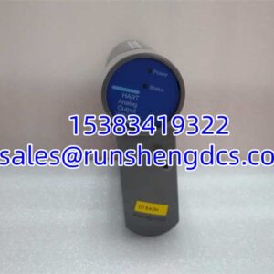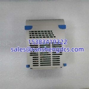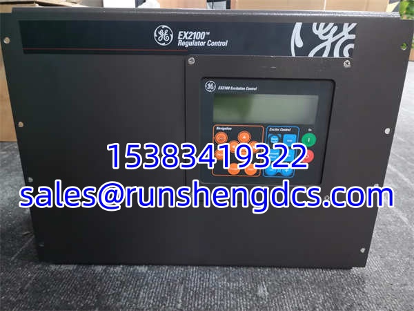

Description
Product Introduction
The GE 3VWWZ036CD001 is a specialized energy control module designed to manage excitation power units in critical turbine and generator applications. In plain terms, it acts as the brain for the excitation system, using Pulse Width Modulation (PWM) to precisely regulate the flow of energy and maintain stable generator voltage.
What makes this module a reliable workhorse is its robust industrial design. It takes a standard 120V input and steps it down to a 24V control output at up to 2A. Housed in a compact 50mm x 50mm x 10mm form factor, it’s built to survive harsh plant environments, boasting an impressive operating temperature range of -40°C to 85°C. Whether you’re dealing with a turbine overhaul or a sudden excitation system fault, this module ensures your generator’s magnetic field remains perfectly controlled.
Key Technical Specifications
| Parameter | Specification |
|---|---|
| Input Voltage | 120 V |
| Output Voltage | 24 V |
| Maximum Current | 2 A |
| Control Method | PWM (Pulse Width Modulation) |
| Operating Temperature | -40°C to +85°C |
| Storage Temperature | -55°C to +125°C |
| Dimensions | 50 mm x 50 mm x 10 mm |
| Primary Application | Excitation Control Systems / Turbines |
| Related GE Models | 369-C100, 469-P5-HI-A20-E-H |
| Form Factor | Compact Energy Control Module |
Compatibility & Replacement Matrix
- GE 3VWWZ036CD001 → GE 3VWWZ036CD001 : Direct Replacement — Identical part number, plug-and-play for excitation systems.
- GE 3VWWZ036CD001 → GE 369 Series (e.g., 369-HI-R-M-F-E-H-E) : Needs Adaptation — The 369 series are motor management relays. While they share the GE ecosystem, they serve different primary functions. Cross-referencing is required for specific excitation protection tasks.
- GE 3VWWZ036CD001 → GE 469-P5-HI-A20-E-H : Incompatible — The 469 series is a generator management relay. It is not a direct drop-in replacement for this specific PWM energy control module.
- GE 3VWWZ036CD001 → ABB PCD235A101 : Incompatible — Although ABB manufactures similar excitation control tasks for power systems, cross-brand substitution in critical excitation loops is strongly discouraged without a full system engineering review.
Quality Inspection & SOP Transparency
Excitation modules are critical for grid stability, so we don’t cut corners on testing:
- Incoming Inspection: We verify the part number (3VWWZ036CD001) and inspect the compact 50x50mm board for any signs of thermal stress, especially around the PWM switching components and the input/output terminals.
- Live Functional Test: We install the module into a test bench simulating a 120V AC/DC source. Using an oscilloscope, we verify the PWM signal integrity and ensure the output cleanly regulates to 24V under a 2A resistive load.
- Electrical Parameter Test: We perform a load regulation test to ensure the 24V output does not sag when the excitation field demands maximum current. We also verify the isolation between the 120V input side and the 24V control side.
- Thermal Verification: Given the -40°C to 85°C operating spec, we review the module’s thermal history (if refurbishing) and ensure the heat dissipation paths on the PCB are intact.
- Final QC & Packaging: After passing functional validation, we seal the module in an anti-static bag with desiccant and pack it in a shock-absorbent carton to protect the compact form factor during transit.
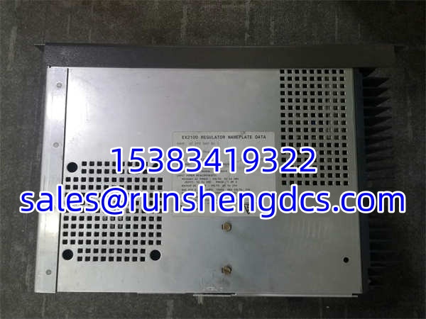
GE 3VWWZ036CD001
Common Replacement Pitfalls
- ❗ PWM Parameter Matching: This module uses PWM control. If you are replacing a failed unit, ensure the new module’s firmware or internal dip-switch settings match the exact excitation system tuning parameters. A mismatch can cause generator voltage hunting or instability.
- ❗ Input Voltage Spikes: The module is rated for 120V input, but excitation systems can experience severe transients during grid faults. Always verify that the upstream snubber circuits or surge protectors are functional before installing a new module.
- ❗ Thermal Environment: While rated to 85°C, mounting this module directly next to a high-current silicon rectifier bridge (SCR) without adequate airflow will drastically reduce its lifespan. Ensure the control cabinet cooling fans are operational.
- ❗ Field Wiring Polarity: The 24V output drives the exciter field. Reversing the polarity during installation can cause a loss of generator voltage or damage the rotating rectifier assembly. Double-check your wiring diagrams against the physical terminal markings.
FAQ
Q: Can I hot-swap this module while the generator is online?
A: Absolutely not. This module controls the excitation power unit. Removing it while the generator is synchronized to the grid will cause a sudden loss of field, leading to a generator trip and potential grid instability. This must be replaced during a scheduled outage or with the generator completely isolated and de-energized.
Q: My old module has a slightly different suffix. Is this 3VWWZ036CD001 compatible?
A: GE excitation modules often have revision suffixes indicating minor component changes or firmware updates. The base 3VWWZ036CD001 is generally backward compatible, but you should verify the exact revision required by your excitation system manual to avoid PWM timing mismatches.
Q: What happens if the 2A max current is exceeded?
A: The module features internal current limiting and protection. If the excitation field demands more than 2A, the PWM duty cycle will limit the output, or the module will fault out to protect itself. If you consistently hit this limit, your exciter field may have a shorted turn, or you may need to upgrade to a higher-capacity power unit.
Q: Does this module communicate over a network?
A: The 3VWWZ036CD001 is primarily an analog/PWM control module. It typically interfaces with a higher-level excitation controller (like a GE Multilin 369 or 469 relay) which handles the digital communications (Modbus, Profibus, etc.). This module executes the raw power control commands.
Q: How do I test this module on the bench?
A: You need a variable 120V source, a 24V/2A electronic load, and an oscilloscope. Apply 120V, connect the load, and monitor the PWM output waveform. The duty cycle should vary smoothly as you adjust the control reference, and the output voltage should remain stable at 24V regardless of load changes up to 2A.