
Description
Key Technical Specifications
- Product Model: 369-HI-0-M-0-0
- Manufacturer: General Electric (GE Multilin)
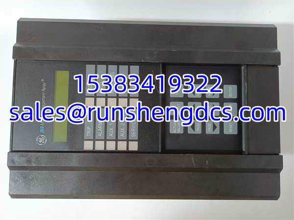
- Product Type: Motor Management Relay
- Primary Function: Motor Protection, Control, & Monitoring
- Protection Features: Overload, Short Circuit, Undervoltage, Overvoltage
- Monitoring: RTD Inputs, Current, Temperature, Vibration
- Communication: RS485 / Modbus (Verify specific option)
- Control Logic: Start/Stop/Reverse, Programmable Logic
- Diagnostics: Event Recording, Fault Analysis
- Display: LED Status Indicators, LCD/Keypad Interface
- Mounting: Panel Mount / DIN Rail
- Condition: Refurbished / Tested (Verify with vendor)
Product Introduction
Motor trips on overload, but the thermal model says it should be fine. The GE 369-HI-0-M-0-0 is the exact relay you need to diagnose the real issue. Sitting in the MCC bucket, this isn’t just a bimetallic strip; it’s a digital brain for your motor. It tracks thermal capacity, monitors RTDs, and records the exact waveform of the fault before tripping, so you stop guessing and start fixing.
Bottom line—this relay pays for itself on the first saved motor. The 369-HI-0-M-0-0 integrates protection, control, and metering into one box. It handles the dirty work of distinguishing between a harmless start-up surge and a genuine locked rotor, using programmable logic to match your specific load curve. Sourcing these today means relying on verified refurbished units, but getting the right firmware revision prevents a $50k motor burnout caused by a misconfigured protection curve.
Troubleshooting Quick Reference
- Nuisance Trips / Overload: 70% chance of incorrect thermal class or start time settings. Check the “Start Time” and “Thermal Class” parameters. Verify actual start current vs. relay setting.
- Comm Loss / Modbus Fail: 80% chance of termination resistor or baud rate mismatch. Check RS485 A/B wiring. Verify 120Ω termination at the ends.
- RTD Fault / Open Circuit: Sensor wiring issue. Measure resistance at the relay terminals. Verify 3-wire vs. 2-wire configuration in settings.
- Display Blank / No Power: Control power failure. Measure 110/220VAC or 24VDC at the input terminals. Check the internal fuse (if accessible).
- False Ground Fault: Capacitive coupling or dirty sensor. Check the ground fault sensor wiring. Verify the “Ground Fault Pickup” setting isn’t too sensitive for VFD applications.
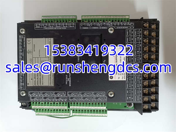
GE 369-HI-0-M-0-0
Application Scenarios & Pain Points
- Water & Wastewater: Driving large vertical turbine pumps. Requires precise thermal modeling to handle frequent starts without nuisance trips.
- Oil & Gas Processing: Compressors and extruders in hazardous areas. Needs reliable RTD monitoring and fast short-circuit protection to prevent catastrophic failure.
- Mining & Metallurgy: Conveyor drives and crushers. High-vibration environments where standard relays fail; the 369’s solid-state design holds up.
- Power Generation: Boiler feed pumps and ID fans. Legacy GE systems need reliable spares to avoid full-MCC upgrades during outages.