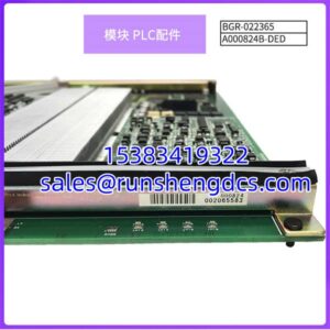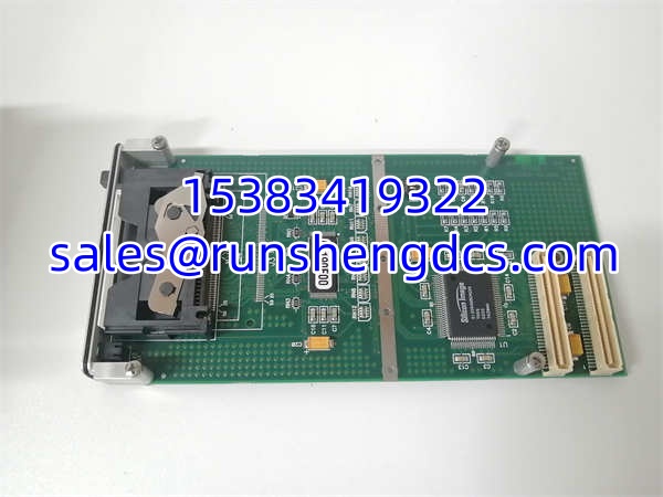

Description
Key Technical Specifications
- Architecture: RISC-based FPPA (Field Programmable Processor Array)
- Processing Cores: Dual 8-bit FPPA cores
- Program Memory: 4K x 16 bits OTP
- Data Memory: 208 Bytes
- ADC Resolution: 12-bit, 11 Channels (1 channel dedicated to internal Band-gap)
- Instruction Set: 101 instructions, mostly single-cycle (1T)
- Clock Sources: Internal High/Low RC (IHRC/ILRC), External Crystal
- Operating Voltage: 2.2V to 5.5V
- Operating Temperature: -40°C to 85°C
- I/O Drive Capability: 10mA per pin
- Hardware Timers: 16-bit counter, 8-bit counter with PWM output
- Package Options: SOP-20, DIP-20, SOP-24, SOP-28
Product Introduction
Legacy automation systems often face a bottleneck when trying to process high-frequency analog sensor data alongside standard digital logic on a single core. The PMC234 was engineered to solve this specific architectural limitation by utilizing dual parallel processing units rather than relying on traditional sequential execution.
This module functions as a high-precision microcontroller or host bus adapter within industrial control architectures. Engineers select this part for its ability to execute most instructions in a single clock cycle while maintaining a 12-bit ADC for accurate sensor feedback. With an operating temperature range of -40°C to 85°C and dual FPPA cores, it handles concurrent signal conditioning and control logic without the latency typical of standard 8-bit MCUs.
QA/QC Transparency SOP
- Intake & Origin Verification: Trace lot codes against original OEM manifests to confirm genuine PADAUK/FORCE silicon and rule out counterfeit clones.
- Live Functional Testing: Load test firmware onto an evaluation board to verify dual-core FPPA synchronization and ADC sampling accuracy.
- Electrical Parameter Tests: Use Fluke multimeters and bench power supplies to validate 2.2V-5.5V operating thresholds and check for ESD damage on I/O pins.
- Firmware/Config Verification: Read OTP memory via programmer to ensure no bit-rot or corrupted program sectors exist on the die.
- Final QC & Anti-Static Packaging: Inspect physical pins for oxidation, vacuum-seal in ESD-safe bags with humidity indicator cards, and attach a serialized QC tag.
Field Engineer Gotchas
- OTP Memory Lock: This chip uses OTP (One-Time Programmable) memory. If you are replacing a failed unit, you cannot simply flash new firmware to a blank chip without an OTP programmer. Bottom line — if the original mask ROM is lost, the replacement is a paperweight.
- PA5 Open-Drain Trap: PA5 is strictly open-drain output. Forgetting the external pull-up resistor will result in floating logic states. I’ve seen entire sensor networks fail because a junior tech assumed standard push-pull behavior.
- Interrupt Core Restriction: Only the FPPA0 core can handle interrupts (ENGINT/DISGINT instructions). Attempting to configure interrupts on FPPA1 will silently fail. Always verify your interrupt vector assignments during code migration.
- PC Port Register Mapping: Port C lacks a dedicated digital input enable register. PC inputs are tied to PB port configuration (PBDIER). Misconfiguring this shared register disables wake-up functions and digital reads on Port C.

FORCE PMC234
Application Scenarios
- Robotic Arm Force Feedback: Mechanical arms require simultaneous 12-bit ADC sampling from load cells and real-time PWM motor control, demanding parallel processing to prevent control loop latency.
- Industrial Sensor Signal Conditioning: Factory floor environments with high EMI need localized analog-to-digital conversion at the sensor node to prevent noise corruption over long cable runs.
- Automated Assembly Line Monitoring: High-speed packaging equipment requires sub-millisecond response times for optical sensor triggers, which single-cycle instruction execution provides reliably.
FAQ
- Is the PMC234 still in active production?
No. PADAUK has marked this series as discontinued. Procurement is limited to surplus, new-old-stock, or refurbished inventory. Always verify shelf-life and storage conditions. - Can I use a standard EEPROM programmer to flash this chip?
No. PMC234 uses OTP memory, not EEPROM. You need a dedicated OTP programmer compatible with PADAUK’s FPPA architecture. Standard EEPROM programmers will not recognize the device. - What is the maximum ADC sampling rate?
The datasheet specifies a 12-bit resolution but does not guarantee a fixed ksps rate across all clock configurations. Verify your specific clock source and prescaler settings against the OEM timing diagrams before finalizing sensor polling rates. - Will a PMS234 drop-in replace a PMC234?
They share the same core architecture, but PMC234 is the high-EFT (anti-interference) variant rated for -40°C to 85°C. PMS234 is the general-purpose version. Substituting PMS234 in a high-noise industrial environment risks intermittent failures. - Why does my Port C input not trigger wake-up?
Port C’s digital input and wake-up functions are mapped to the PBDIER register, not a dedicated PCDIER register. Setting PBDIER.x = 1 enables both PB.x and PC.x. This shared mapping is a common migration pitfall from other MCU families. - What is the ESD tolerance on the I/O pins?
The datasheet does not specify a standard HBM rating for this legacy part. Assume minimal ESD protection. Always use proper grounding and anti-static handling during installation. Verify with OEM datasheet before deployment in high-static environments.