
Description
Key Technical Specifications
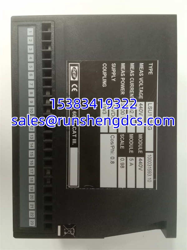
- Product Model: LSU-112DG 100031593.10
- Manufacturer: DEIF
- Product Category: Load Sharing & Parallel Control Unit
- Power Supply: 24 Vdc / 120 Vac
- Output Frequency: 50-60 Hz
- Control Mode: Isochronous (Parallel) / Droop (Island)
- Interface: Electronic Potentiometer (EPQ96-2 / EPN110DN)
- Built-in Transducers: Active Power & Frequency
- Speed Control Outputs: 2 Relay Contacts
- Application: Diesel & Gas Generator Paralleling
Product Introduction
When you drop a heavy load onto a single generator, the engine bogs down; when you do it across three generators, the load must split perfectly or the weakest unit trips offline. The DEIF LSU-112DG 100031593.10 is the dedicated load sharing unit designed to solve this exact problem. It acts as the traffic cop for parallel generator sets, continuously monitoring frequency and active power, and adjusting the governor setpoints to ensure the kW load is distributed evenly across all online machines.
Engineers specify the DEIF LSU-112DG 100031593.10 because it bridges the gap between analog governors and modern digital control. By communicating through electronic potentiometers like the EPQ96-2 or EPN110DN, this module translates precise load-sharing algorithms into physical speed adjustments. Bottom line — it takes the guesswork out of paralleling, ensuring your diesel or gas gensets run in perfect synchronization without circulating currents tearing up your alternators.
QA/QC Transparency SOP
- Intake & Origin Verification: We verify the specific 100031593.10 part number and inspect the LSU-112DG for physical damage, checking the DIN rail clips and terminal blocks for stress fractures.
- Live Functional Testing: The module is powered up on a 24Vdc test bench to verify the internal power supply and check the status of the built-in frequency and power transducers.
- Electrical Parameter Tests: We use a calibrated multimeter to verify the relay outputs for speed control and ensure the analog outputs match the expected scaling for the EPQ96-2 interface.
- Firmware/Config Verification: We read the DIP switch settings and internal configuration to ensure the unit matches the required base load or isochronous parameters.
- Final QC & Anti-Static Packaging: The LSU-112DG is sealed in an ESD-safe bag with desiccant to prevent moisture ingress on the PCB during long-term storage.
Field Engineer Gotchas
- Governor Interface Mismatch:
Risk: The LSU-112DG is designed to work with specific electronic potentiometers (EPQ96-2 or EPN110DN). If you wire it directly to an analog voltage governor input without the proper interface, you will get erratic load sharing.
Solution: Verify the exact governor model and ensure the correct DEIF potentiometer is installed.
Warning: I’ve seen techs wire this directly to a Woodward governor expecting magic. It doesn’t work. Respect the signal chain. - Base Load vs. Isochronous Confusion:
Risk: If the is configured for base load but the system is running in isochronous mode, the generator will either hog all the load or drop it entirely.
Solution: Double-check the hardware DIP switches and software parameters against the system’s single-line diagram.
Warning: Always take a photo of the old module’s DIP switches before pulling it. Guessing the switch settings is a great way to cause a blackout. - Potentiometer Calibration:
Risk: Even with a perfect , if the electronic potentiometer is out of calibration, the load sharing will be skewed.
Solution: Perform a full load-share calibration test using a calibrated power analyzer.
Warning: Don’t just swap the module and assume it’s fixed. The problem might be the actuator at the governor.
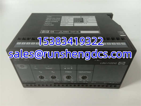
DEIF 100031593.10 LSU-112DG
Application Scenarios
- Marine Vessel Power Plants: Ships rely on the DEIF 100031593.10 to manage multiple diesel generators in the engine room, ensuring that when a heavy thruster kicks in, both generators share the transient load without tripping.
- Data Center Backup Power: Critical facilities use the to parallel redundant generator sets, guaranteeing that no single engine is overloaded during a grid failure and extended runtime.
- Microgrid & Peak Shaving: Industrial plants use the to synchronize onsite generation with utility power, actively exporting excess power to the grid or shedding load during peak tariff hours.
FAQ
No. The is strictly for active power (kW) and frequency sharing. Reactive power (kVAR) and voltage control are handled by a separate unit, like the DEIF AGC-4 or a dedicated voltage regulator.
Is this module compatible with mechanical governors?
Yes, but it requires the OPR-1 relay output board (often found in the SCM-1 module) to convert the digital signals into mechanical raise/lower pulses.
The generators will lose synchronization. They will revert to droop mode or island mode, and the load sharing will become unstable. This is why redundant cabling is critical in marine applications.
Does the 100031593.10 suffix matter?
Yes. DEIF frequently updates internal components and firmware. The 100031593.10 suffix ensures you are getting the exact hardware revision required for your specific system configuration.
Can I use this for a single standalone generator?
Technically yes, but it’s overkill. For a single generator, you just need a standard AGC controller. The is specifically designed for the complex math of paralleling multiple sources.
How do I calibrate the load sharing?
You need to apply known loads and adjust the gain and integral parameters in the DEIF configuration software while monitoring the kW output of each generator. It’s an iterative process. Don’t rush it.