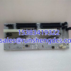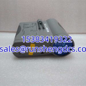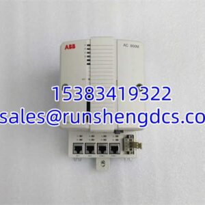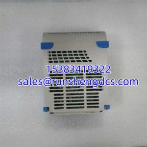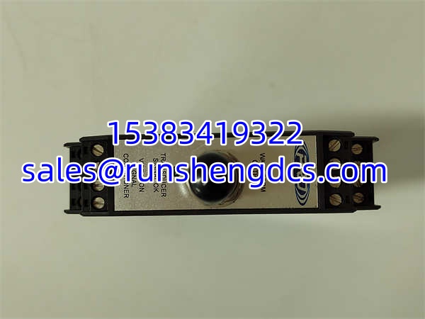

Description
Key Technical Specifications
| Parameter | Detail |
|---|---|
| Model | SC203-100A-002IR-010-01K-05 |
| Manufacturer | CTC (Connecticut Technologies Corporation) |
| Product Series | SC200 Series |
| Product Type | Signal Conditioner (Vibration & Temperature) |
| Input Power | 24 to 32 VDC unregulated, 225 mA max |
| Sensor Excitation | 24 VDC, 4 mA DC |
| Output Signal | 4-20 mA (primary); optional 0-5 VDC or 0-10 VDC |
| Max Load Resistance | 600 ohms |
| Isolation | 1000 VDC |
| Operating Temperature | -40°C to +70°C (-40°F to +158°F) |
| Humidity | 0-95% RH, non-condensing |
| Mounting | 35 mm DIN rail |
| Connector Type | Screw-type terminal block, removable |
| Weight | 0.15 kg |
| Accepted Inputs | Acceleration, velocity, temperature, displacement |
| Configuration | Internal DIP switches for field configuration |
| Certification | CE |
Product Introduction
Vibration monitoring in rotating machinery demands more than just a sensor — it demands a signal conditioner that can take raw accelerometer or velocity data, filter out noise, and hand the control room a clean 4-20 mA signal that a DCS or PLC can actually use. The CTC SC203-100A-002IR-010-01K-05 is exactly that device: a member of the SC200 series signal conditioners built to accept vibration inputs (acceleration, velocity, displacement) and temperature, then output proportional process signals for machinery protection and condition monitoring systems.
What sets the SC203 apart from a basic transmitter is its dual-band capability. It provides a steady 4-20 mA output for real-time process monitoring while simultaneously offering a buffered dynamic output (via BNC jack and screw terminals) for connection to traditional vibration data acquisition systems. Internal DIP switches let field technicians configure input scaling, filter settings, and output ranges without pulling the unit off the DIN rail. The 1000 VDC isolation between input and output sides protects downstream control electronics from ground loops and transient spikes — a real concern when mounting signal conditioners near large motors or generators.
QA/QC Transparency SOP
For surplus or refurbished SC203 units, a competent vendor should verify:
- Intake & Visual Inspection — Confirm the full model number “SC203-100A-002IR-010-01K-05” is legible on the label. Inspect the PCB for cracked solder joints, corroded traces, or damaged terminal blocks. Verify the DIN rail clip is intact and functional.
- Power-Up Test — Apply 24 VDC to the unit and measure current draw. It should not exceed 225 mA. Confirm the unit powers up without excessive heat generation or abnormal behavior.
- Signal Injection & Output Verification — Inject a known test signal (e.g., a calibrated 4-20 mA current loop or a reference voltage simulating sensor input). Measure the output at the terminal block and confirm it tracks proportionally within expected accuracy tolerances.
- Isolation Test — Using a megger or high-potential tester, verify the 1000 VDC isolation barrier between input-side circuits and output-side circuits. Any breakdown below spec means the unit fails.
- DIP Switch & Configuration Check — Toggle each DIP switch position and confirm the unit responds to configuration changes (output range, filter settings). Document the switch positions before shipping so the buyer can replicate their existing setup.
Field Engineer Gotchas
- Isolated Commons Required — Each 4-20 mA output on the SC203 requires its own isolated common wire. Do not share a common return between multiple outputs. Sharing commons defeats the isolation and can introduce ground loop errors or damage the output drivers. I have seen plants wire two outputs to a shared ground bus and then wonder why their vibration readings drift.
- DIP Switch Documentation — Before pulling a failed unit, photograph or document the DIP switch positions. The replacement will arrive with factory-default switch settings. If you install it without matching the original configuration, the output scaling will be wrong — and you will spend hours chasing a “sensor fault” that is actually a configuration mismatch.
- Sensor Power On/Off — The SC203 has a sensor power on/off option. If your application uses dual-band configuration with multiple signal conditioners, make sure sensor power is enabled on the correct unit and disabled on the one receiving the buffered signal. Enabling power on both can overload the sensor excitation circuit.
- Input Type Mismatch — The accepts acceleration, velocity, temperature, and displacement inputs — but the DIP switch configuration must match the actual sensor type connected. Feeding an accelerometer signal into a unit configured for velocity input will produce garbage output. Verify the switch settings against the sensor datasheet.
- Load Resistance Limit — Maximum load resistance is 600 ohms. If your control system input card has high internal resistance or there is significant cable resistance in a long run, you may exceed this limit. Calculate total loop resistance before installation.
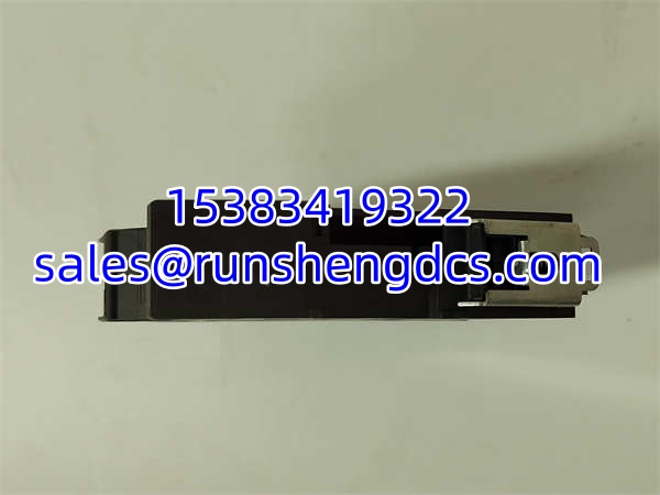
CTC SC203-100A-002IR-010-01K-05
Application Scenarios
- Rotating Equipment Protection — Turbines and Compressors: The conditions vibration signals from accelerometers mounted on turbine bearings, converting raw vibration data into 4-20 mA alarm and trip signals for the plant DCS. The buffered output feeds a portable data collector for route-based vibration analysis.
- Pump Station Monitoring — Water/Wastewater: Municipal pump stations use modules to monitor bearing vibration and motor temperature on large centrifugal pumps. The 4-20 mA output drives SCADA trending, while the dynamic output captures waveform data during troubleshooting events.
- Fan and Blower Monitoring — HVAC and Process Air: Industrial fans in power plants and chemical facilities mount accelerometers on bearing housings. The converts the signal for continuous monitoring, providing early warning of imbalance, misalignment, or bearing degradation.
- Paper Mill — Dryer Roll Vibration: Paper machine dryer rolls operate at high speed with tight vibration tolerances. conditioners mounted on the DIN rail in the MCC room provide real-time vibration trending to the DCS, with the dynamic output available for periodic route-based analysis.
Real-World Context: In a typical power plant, an monitoring a forced-draft fan bearing detects rising vibration over several weeks. The 4-20 mA trend in the DCS triggers a maintenance work order before the bearing reaches alarm setpoint. During the outage, the technician connects a data collector to the BNC buffered output, captures waveform data, and confirms inner-race bearing defect frequency — validating the replacement decision before the bearing fails catastrophically.
FAQ
What is the difference between the SC203 and other SC200 series models?
The SC200 series covers various signal conditioning configurations. The specifically handles dual-band vibration and temperature inputs with 4-20 mA plus optional voltage outputs. Other models in the series may handle single-band vibration only or different input/output combinations. Check the full part number against CTC documentation to confirm functional equivalence.
Can I use this with a 4-20 mA HART transmitter?
No. The is a signal conditioner for raw sensor inputs (accelerometers, velocity sensors, RTDs, thermocouples), not a HART communicator or repeater. It conditions analog sensor signals into process-standard outputs.
What programming tool do I need?
No software tool. Configuration is done entirely through internal DIP switches. This is by design — it eliminates the need for a laptop in the field and makes the unit functional immediately after power-up.
Is the 0-5 VDC or 0-10 VDC output available simultaneously with the 4-20 mA?
Yes. The provides the 4-20 mA output as the primary process signal, with an optional voltage output (selectable between 0-5 VDC or 0-10 VDC) proportional to the same vibration level. Both are available from the same unit.
What does the “IR” in the part number indicate?
The part number encoding follows CTC’s configuration naming convention. The “IR” segment likely indicates specific input range or filter configuration options. For exact decoding, refer to the CTC product selector guide or contact the manufacturer — surplus sellers rarely decode these suffixes accurately.
Can I mount this in a hazardous area?
The is CE-certified, but the available documentation does not confirm intrinsic safety or explosion-proof ratings. If you need to install in a classified hazardous area, verify the specific certification markings on the unit label before installation. Do not assume it is rated for Class I, Division 1 or Zone 0/1 without confirmed markings.