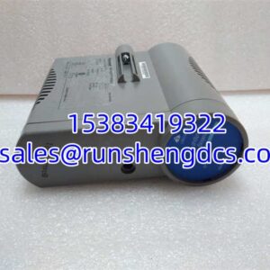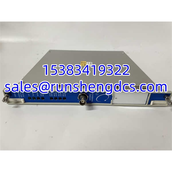

Description
Key Technical Specifications
| Parameter | Value |
|---|---|
| Function | Electronic overspeed/tachometer detection |
| System Platform | Bently Nevada 3500 Machinery Protection System |
| Sensor Input | Eddy-current probe or magnetic pickup |
| Input Signal Range | +10.0 V to -24.0 V (clamped internally) |
| Input Impedance | ~20 kΩ |
| Supported Sensors | Bently Nevada 3300 8 mm, 3300 16 mm HTPS, 7200 5/8/11/14 mm, 3300 RAM, or magnetic pickup |
| Speed Range | Up to 99,999 rpm |
| Max Input Frequency | 20 kHz |
| Min Input Frequency | ~0.0167 Hz per event for eddy-current; ~3.3 Hz for passive magnetic pickup |
| Events per Revolution | 1 to 255 |
| Resolution | ~0.3662 µA per bit (recorder output) |
| Recorder Output | 4–20 mA proportional to rpm |
| Buffered Output | Front-panel coaxial sensor buffer output |
| Relay Contacts | Up to 5 A; 250 Vac / 30 Vdc (verify per revision) |
| Power Consumption | ~8.0 W typical |
| Redundancy | 2oo2 or 3oo2 voting; 3oo2 recommended |
| Operating Temperature | Typically -30°C to +65°C for 3500 rack systems |
| Configuration | Via 3500 Rack Configuration Software |
Product Introduction
The 3500/53 is not a general-purpose vibration or position monitor — it is purpose-built for overspeed protection. That distinction matters because overspeed is one of the few faults where the protection system must respond in milliseconds, and a wrong reading or a stuck relay can be catastrophic. The 133388-01 module accepts a single speed sensor input (eddy-current probe or magnetic pickup), converts it into a precise tachometer signal, and compares the measured speed against configured Alert and Danger setpoints.
Multiple 3500/53 modules are installed in adjacent slots and configured as a group. The first module’s configuration is copied to the others, creating a 2oo2 or 3oo2 voting system. The 3oo2 arrangement is recommended because it tolerates a single sensor or module fault without tripping or blocking protection. Each module provides a buffered sensor output for external verification, a 4–20 mA recorder output, and relay contacts that can drive trip circuits through a 3500/32 or 3500/34 relay module.
This is a safety-critical module. It should not be treated as a plug-and-play spare. Configuration, setpoint verification, and voting logic must be validated against the turbine protection narrative before the module is returned to service.
QA/QC Transparency SOP
- Intake & Origin Verification — Confirm Bently Nevada part number 3500/53, serial 133388-01, and revision markings. Reject units with damaged front-panel connectors, bent DIN pins, cracked housings, or corrosion on the backplane interface.
- Visual Inspection — Check coaxial sensor output connector, LED indicators (OK, TX/RX, Bypass, Test Mode, Alarm), and module labeling. Verify no evidence of prior overheating or connector rework.
- Live Functional Testing — Install in a verified 3500 rack with compatible 3500/15 power supply and 3500/20 or 3500/22M rack interface. Apply a calibrated frequency source simulating eddy-current or magnetic pickup input. Verify rpm reading accuracy across low, mid, and high speed points.
- Setpoint & Relay Verification — Download a test configuration with known Alert and Danger setpoints. Confirm relay actuation at the correct trip points. Verify 4–20 mA recorder output scales correctly with speed.
- Final QC & Packaging — Record test results, clear test configuration or restore site-approved configuration only under authorization, seal in ESD packaging, and document condition as new surplus, refurbished, or tested working.
Field Engineer Gotchas
- It is a single-channel module. One 3500/53 does not provide redundant protection by itself. You need two or three modules in a voting group. Installing only one and expecting overspeed protection is a serious gap.
- Configuration must be downloaded. A blank or mismatched 3500/53 will not trip correctly. After replacement, the module must receive the correct group configuration from the 3500 Rack Configuration Software.
- Mating I/O matters. The 133388-01 monitor module mates with the 3500/53 I/O terminal (commonly 133396-01). Swapping the monitor without verifying the I/O terminal can leave the sensor input unconnected or miswired.
- Magnetic pickup low-speed limitation. Passive magnetic pickups require sufficient rotational speed to generate a usable signal. At very low speeds, the module may not detect rotation reliably. Eddy-current probes are preferred for full-range coverage.
- Do not use general 3500 relays for overspeed trip. Overspeed trip circuits should use the dedicated overspeed relay path. General alarm relays in the rack are not an acceptable substitute for the overspeed protection trip channel.
- Firmware and software compatibility. Adding a 3500/53 to an existing rack may require minimum firmware levels on the 3500/20 RIM and compatible Rack Configuration Software versions. Check compatibility before downloading configuration.
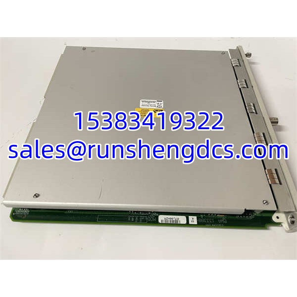
Bently Nevada 3500/53 133388-01
Application Scenarios
- Steam turbine overspeed protection. Monitors shaft speed via a gear tooth or keyphasor probe. Multiple 3500/53 modules form a 3oo2 trip system tied to the turbine trip solenoid circuit.
- Gas turbine compressor train protection. Provides independent speed monitoring for each shaft in a multi-shaft train. The buffered output allows a separate governor or diagnostic system to cross-check speed.
- Industrial compressor anti-overspeed. Used where the driver governor may fail and a mechanical or electronic overspeed trip is required by API 670 / API 612.
- Case note: A refinery replaced a failed 3500/53 during a turnaround but did not reload the overspeed group configuration. The module powered up with OK LED lit, but the Danger setpoint was at default. During commissioning, the speed simulation test tripped at the wrong rpm. The module was functional — the configuration was missing. After reloading the approved .rak file and verifying 3oo2 voting, the group passed acceptance testing.
FAQ
Is 133388-01 the complete overspeed channel?
No. It is the monitor module. A complete channel also requires the mating I/O terminal (typically 133396-01), a speed sensor, proper cabling, and a downloaded configuration.
Can I install just one 3500/53?
You can install one, but it will not provide redundant overspeed protection. API 670-compliant overspeed systems typically use 2oo2 or 3oo2 voting with multiple modules.
What sensors can it accept?
Bently Nevada eddy-current probes (3300, 7200 families) and magnetic pickups. The input range is +10.0 V to -24.0 V, clamped internally.
Does it replace the 3500/50?
No. The 3500/50 is a general tachometer/speed monitor. The 3500/53 is specifically designed for overspeed protection voting systems.
What software configures it?
Bently Nevada 3500 Rack Configuration Software (3500/01). Configuration is downloaded through the 3500/20 or 3500/22M rack interface module.
Why does the Alarm LED stay on after replacement?
Common causes include missing configuration, incorrect sensor input, open sensor circuit, or a setpoint already exceeded by the current speed. Check the configuration download and sensor signal first.
Can this module be hot-swapped?
3500 monitor modules are generally hot-swappable in a powered rack, but overspeed modules should be replaced under a controlled procedure. Verify that the remaining modules in the voting group maintain protection during the swap.