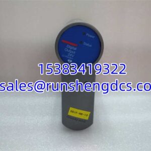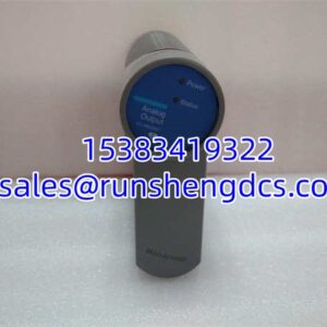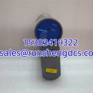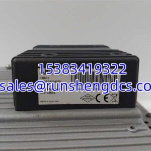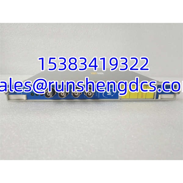

Description
Key Technical Specifications
| Parameter | Specification |
|---|---|
| Channels | 4 independent channels |
| Supported sensors | Proximitor, velocity, accelerometer |
| Measurement types | Radial vibration, thrust position, differential expansion, eccentricity, REBAM, absolute shaft vibration |
| Analog outputs | 1 × 4–20 mA per channel (recorder output) |
| Relay outputs | 2 per channel (Alarm / Danger), mapped via 3500/32 or 3500/34 |
| Power | +24 V DC from 3500 rack backplane |
| Typical power draw | ~7.7 W |
| Accuracy | ±0.33% FS typical; up to ±1% max depending on filtered parameter |
| Resolution / sampling | 24-bit A/D; up to 102.4 kHz sampling |
| Operating temperature | -30 °C to +65 °C (rack-dependent) |
| Safety / standards | SIL 2 capable; API 670 compliant |
| Hot-swap | Supported in redundant 3500 rack |
Product Introduction
A turbine trip during startup is rarely a software problem. It is usually a sensor wiring fault, a drifted setpoint, or a monitor module that was swapped without verifying the configuration. The Bently Nevada 3500/42M sits directly in that trip path. Installed in a 3500 rack, it takes raw signals from proximitor probes, velocity sensors, and accelerometers, converts them into engineered vibration and position values, and compares them against Alarm and Danger setpoints. If a threshold is breached, the relay outputs drive the trip logic through a 3500/32 or 3500/34 relay module.
What separates the 42M from the older 3500/40M is flexibility. The 40M handles displacement-type measurements well. The 42M adds velocity and accelerometer support, so one card can cover radial shaft vibration, thrust position, differential expansion, eccentricity, and casing vibration. Each channel delivers a dedicated 4–20 mA recorder output, which matters when the DCS needs live trend data independent of the trip relays. With 24-bit resolution and SIL 2 capability in a properly configured rack, it remains a workhorse for API 670-compliant TSI systems.
QA/QC Transparency SOP
- Intake & Origin Verification — Verify full part number (176449-02, 140734-02, or other), serial number, and source documentation. Reject units with burned connectors, cracked housings, or missing rear I/O modules.
- Live Functional Testing — Install in a verified 3500 rack with a known-good 3500/15 power supply and 3500/22M or 3500/20 RIM. Confirm OK, TX/RX, and Bypass LEDs behave correctly. Upload existing configuration via 3500 Configuration Software and verify channel status.
- Electrical Parameter Tests — Check backplane power draw against the ~7.7 W typical spec. Validate 4–20 mA outputs with a Fluke or equivalent loop calibrator. Test relay contact continuity for Alarm and Danger states.
- Firmware/Config Verification — Read firmware revision and compare it to the site baseline. Export and hash the configuration file. Flag any mismatch before the card goes near a live turbine.
- Final QC & Anti-Static Packaging — Seal in ESD bags with desiccant. Include a test report showing power draw, 4–20 mA readings, relay checks, firmware revision, and configuration file hash.
Field Engineer Gotchas
- Firmware revision mismatch. A newer 42M loaded with an old .rak file can behave unexpectedly, especially on filtered channels. Always upload the existing configuration first, then compare setpoints, filter settings, and channel types before downloading.
- 3500/42M vs 3500/40M confusion. The 40M does not provide per-channel 4–20 mA outputs. If your DCS relies on those analog signals, dropping a 40M into a 42M slot will create a silent integration gap.
- Relay outputs are not on the 42M itself. The 42M generates Alarm/Danger states, but the actual trip contacts live on the 3500/32 or 3500/34 relay module. Replacing the 42M without verifying relay association logic can leave the trip matrix broken.
- Hot-swap is not “no-risk.” The 3500 supports hot insertion, but you must bypass associated trips before pulling the card. Otherwise, a momentary loss of monitoring can spuriously energize or de-energize relay outputs depending on the relay module configuration.
- Part number variants matter. Listings show 176449-02, 140734-02, and 128229-01. Some refer to the front monitor, some to the rear I/O module, and some to a combined assembly. Buying the wrong half means the card will not seat or will not terminate sensors correctly.
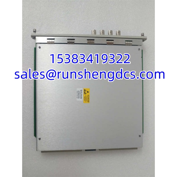
BENTLY 3500-42M
Application Scenarios
- Steam turbine TSI protection. Radial vibration on bearings 1–4, thrust position, and differential expansion monitored continuously. The 42M drives Alarm/Danger relays through a 3500/32 to the ETS.
- Centrifugal compressor train. Proximitor probes on journal bearings plus casing accelerometers on the gearbox. The 42M handles both displacement and seismic inputs in one rack.
- Induced-draft fan monitoring. Eccentricity during slow roll, radial vibration at operating speed, and 4–20 mA feeds to the DCS for trend analysis.
- Reciprocating compressor frame vibration. Accelerometer inputs on the frame and crosshead, with filtered channels to separate mechanical impacts from process pulsation.
FAQ
Q: Is the 3500/42M a direct replacement for the 3500/40M?
A: Mechanically, yes. Functionally, not always. The 42M supports velocity and accelerometer inputs and provides per-channel 4–20 mA outputs. The 40M does not. If your application only needs displacement measurements, a 40M may suffice, but you lose the analog outputs.
Q: Does the 3500/42M have relay contacts on the front?
A: No. The 42M generates Alarm and Danger states internally, but the physical trip relays are on a separate 3500/32 or 3500/34 module. Always verify relay association in the rack configuration.
Q: Can I hot-swap a 3500/42M?
A: Yes, the 3500 rack supports hot insertion. But bypass the associated trips first, confirm the replacement card matches the site firmware baseline, and reload the correct configuration before restoring protection.
Q: What does the 4–20 mA output represent?
A: Each channel can map one measured variable — such as 1X amplitude, direct gap, or overall vibration — to a proportional 4–20 mA signal. The mapping must be confirmed in the configuration software, because it is not fixed by hardware.
Q: Is the 3500/42M SIL 2 certified by itself?
A: It is SIL 2 capable within a compliant 3500 system. SIL certification depends on the full rack architecture, including power redundancy, relay modules, and proven-in-use documentation. Do not claim SIL compliance based on the monitor alone.
Q: Which part number should I order — 176449-02 or 140734-02?
A: Verify against your existing card and the rear I/O module. Different vendors use different numbers for the front monitor, rear terminal module, or combined assembly. Mismatched halves will not function correctly.
Q: Can it monitor differential expansion and thrust position at the same time?
A: Yes, but channels are configured in pairs. Typically, channels 1–2 handle one function and channels 3–4 handle another. Plan slot usage carefully when mixing DDX, thrust, radial vibration, and eccentricity.