
Description
Key Technical Specifications
| Parameter | Value / Note |
|---|---|
| Manufacturer | Bently Nevada (Baker Hughes) |
| System Platform | Bently Nevada 3500 Machinery Protection System |
| Module Type | 3500/32 4-Channel Relay Module |
| Part Number | 125712-01 (spare relay control module); 149986-02 also listed as spare 4-channel relay control module in some sources |
| Configuration | 3500/32-01-00 typical ordering code |
| Relay Channels | 4 independent relay outputs |
| Relay Type | SPDT relays combined as DPDT per channel (two SPDT relays linked) |
| Contact Rating | 5 A at 24 Vdc or 120 Vdc; 250 Vrms arc suppression; 100,000-cycle contact life |
| Alarm Drive Logic | AND/OR logic programmable from any monitor channel Alert/Danger/Not-OK inputs via 3500 Rack Configuration Software |
| Power Consumption | Typical ~5.8–6 W |
| Operating Temperature | -30°C to +65°C (-22°F to +150°F) |
| Storage Temperature | -40°C to +85°C (-40°F to +185°F) |
| Humidity | 95% non-condensing |
| Mounting | Full-height module; installs in any slot to the right of the rack interface/TDI module |
| Standards | API 670 compliant system; CSA/NRTL/C Class I Div 2 approval option available |
| Availability | Surplus / refurbished; verify configuration and test report |
Product Introduction
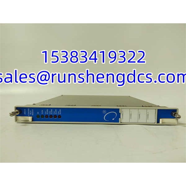
The Bently Nevada 3500/32 125712-01 is the spare 4-channel relay control module for the Bently Nevada 3500/32-01-00 relay module, part of the 3500 machinery protection system. It provides four independently programmable relay outputs that can be driven by alarm conditions from any monitor channel in the 3500 rack — including radial vibration, axial position, differential expansion, speed, and temperature channels. Each relay channel includes alarm-drive logic that can be programmed with AND/OR voting using Alert, Danger, and Not-OK states via the 3500 Rack Configuration Software.
This module is not a standalone controller; it operates within a 3500/05 rack under the configuration managed by the rack interface module or 3500/22M TDI. Its primary role is to convert monitored mechanical conditions into hard-wired relay outputs for turbine trips, compressor shutdowns, alarm annunciation, and DCS/PLC interlocks. For spare procurement, the critical checks are the exact configuration code (3500/32-01-00), the relay logic mapping, the associated I/O module part number, and whether the unit has been functionally tested in a live 3500 rack.
QA/QC Transparency SOP
- Intake & Part Verification — Record full module designation 3500/32-01-00, control module P/N 125712-01, I/O module P/N, serial number, and hardware revision. Reject units with cracked housings, bent backplane connectors, or damaged relay terminal blocks.
- Visual & Mechanical Inspection — Check front-panel LEDs (OK, TX/RX, CH ALARM), relay terminal screws, DIN-rail/backplane engagement, and conformal coating condition. Verify that the associated 125720-01 (or equivalent) I/O module is present if sold as a pair.
- Electrical Pre-Check — Measure insulation resistance on relay contact terminals and backplane pins. Check for shorts on relay coil circuits. Do not apply rack power unless the module is installed in a verified 3500/05 rack.
- Rack Communication & Logic Verification — Install in a compatible 3500 rack with 3500/22M TDI or RIM. Confirm OK and TX/RX LEDs indicate normal communication. Use 3500 Rack Configuration Software to verify relay channel mapping, AND/OR logic, energized/de-energized mode, and alarm response.
- Final QC & Packaging — Label with module code, P/N, rack slot used during testing, relay logic summary, test date, and tester ID. Package in ESD-safe material with configuration printout. Include a traceable test report for site QA review.
Field Engineer Gotchas
- Configuration Loss — The 3500/32 relay logic is stored in the rack configuration, not solely on the module. A replacement module without the correct rack config download will not replicate the original trip logic. Solution: Upload and archive the existing 3500 rack configuration before removing the failed module.
- Wrong I/O Module Pairing — 125712-01 is the relay control module; the rear I/O module (e.g., 125720-01) carries the actual relay contacts. Swapping only one half may leave wiring mismatches. Solution: Verify both front and rear module P/Ns match the original assembly.
- Energized vs. De-energized Mode — Relays can be configured as normally energized or normally de-energized. Installing a module with the wrong mode can cause an unintended trip or failure to trip. Solution: Confirm the relay operating mode in the configuration software before commissioning.
- Slot Position Dependency — Although 3500/32 modules can occupy multiple slots, the rack configuration assigns specific logic to each slot. Installing in the wrong slot breaks the alarm-drive mapping. Solution: Document the original slot location before removal.
- Contact Rating Mismatch — Some 3500 relay I/O variants list different maximum contact ratings. Exceeding the rated load causes premature contact failure. Solution: Verify the actual contact rating on the I/O module label and confirm the connected load is within spec.
- TMR Confusion — The 3500/32 is for standard (non-redundant) relay applications. TMR applications require the 3500/34 TMR relay module. Solution: Do not substitute 3500/32 for 3500/34 in TMR-configured racks.
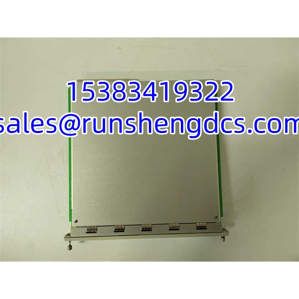
BENTLY 3500-32 125712-01
Application Scenarios
- Turbine/compressor trip relay replacement — Restoring hard-wired trip outputs in a Bently Nevada 3500 machinery protection rack.
- Alarm annunciation interface — Driving plant alarm panels, DCS digital inputs, or PLC interlocks from 3500 monitor channel alarms.
- Legacy 3500 rack maintenance — Replacing a failed 3500/32 relay module where OEM lead times are extended.
- Spare parts inventory — Keeping a pre-verified 3500/32 relay module to minimize protection system downtime during relay faults.
FAQ
1. Is 125712-01 the complete 3500/32 module?
No. 125712-01 is the spare 4-channel relay control module (front card). The complete 3500/32-01-00 assembly typically includes the associated relay I/O module (e.g., 125720-01).
2. How many relay outputs does it provide?
Four independent relay channels, each programmable with AND/OR alarm-drive logic.
3. Can it be used for TMR applications?
No. TMR applications require the Bently Nevada 3500/34 TMR relay module.
4. Does it store the trip logic internally?
The relay logic is defined in the 3500 rack configuration and managed via the 3500 Rack Configuration Software. A replacement module requires the correct rack configuration to operate properly.
5. What is the relay contact rating?
Typically 5 A at 24 Vdc or 120 Vdc with 250 Vrms arc suppression and 100,000-cycle contact life, but confirm on the physical I/O module label.
6. Can it be tested on a bench power supply?
No. The 3500/32 requires a 3500/05 rack, proper backplane power, and communication with the rack interface/TDI module for functional testing.
7. Should I keep a 3500/32 as a spare?
Yes, if your site uses Bently Nevada 3500 racks for machinery protection. A verified spare with documented relay logic can significantly reduce trip-system restoration time.