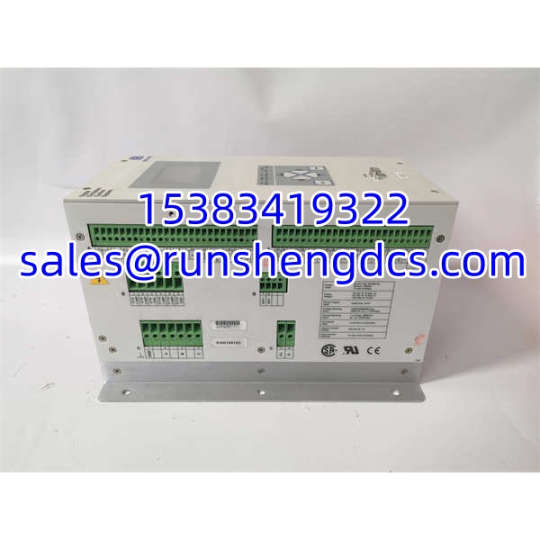

Description
Key Technical Specifications
| Parameter | Value / Note |
|---|---|
| Manufacturer | Basler Electric |
| Model | DECS-200-2L |
| Product Type | Digital Excitation Control System / AVR |
| Application | Synchronous generator excitation control (brushed or brushless exciters) |
| Exciter Output | Up to 125 Vdc, 15 A |
| Voltage Regulation Accuracy | ±0.25% |
| Control Modes | Automatic AVR mode; manual FCR (field current regulator) mode |
| Sensing | True-RMS voltage sensing; PT input (single- or three-phase, 50/60 Hz); CT input 1 A or 5 A for reactive sensing |
| Communication | RS-485 Modbus RTU; RS-232 front-panel port for configuration |
| Configuration Software | Basler BESTCOMS / BESTCOMS Plus |
| Protective Functions | Over/under excitation limiter, V/Hz limiter, over/under voltage protection (27/59), soft-start, stator current limiter, PF/VAR control |
| Redundancy / Parallel | Supports dual-DECS-200 parallel redundancy with bumpless transfer (system-dependent) |
| Control Supply | Typically 24 Vdc or station DC; confirm exact supply from nameplate |
| Mounting | Panel/chassis mount in excitation cabinet |
| Availability | Surplus / refurbished; verify configuration and test report |
Product Introduction
The Basler Electric DECS-200-2L is a microprocessor-based digital excitation control system designed for synchronous generators. It integrates automatic voltage regulation, manual field-current control, protective limiters, and communication interfaces into a single compact module. With up to 125 Vdc at 15 A exciter output and ±0.25% voltage regulation accuracy, it is suitable for a wide range of generator sizes — from industrial gensets to utility and marine applications.
Unlike a simple analog AVR, the DECS-200-2L provides configurable stability settings, event recording, oscillography, PF/VAR control, line drop compensation, and Modbus RTU integration with plant DCS/SCADA systems. The “2L” designation indicates a specific DECS-200 configuration; exact I/O options, control supply voltage, and firmware must be matched against the existing installation. For spare procurement, configuration alignment is as important as the part number.
QA/QC Transparency SOP
- Nameplate & Configuration Verification — Record model -2L, serial number, firmware revision, control supply voltage, CT ratio, PT ratio, and any option codes. Reject units with damaged connectors, burnt components, or missing configuration labels.
- Visual & Mechanical Inspection — Check terminal blocks, communication ports (RS-232/RS-485), fuses, and mounting hardware. Verify that all jumpers and option modules match the original unit.
- Electrical Pre-Check — Measure insulation resistance on power and exciter output terminals. Check control supply input for shorts. Do not apply exciter output voltage without proper load or test setup.
- Functional & Communication Test — Power up with correct control supply. Verify front-panel LCD, LED status, and HMI navigation. Connect via RS-485 Modbus or RS-232 and confirm BESTCOMS communication. Verify AVR mode, FCR mode, and limiter status if test equipment permits.
- Configuration Backup & Final QC — Archive all parameter sets, stability settings, and limiter values. Label with model, firmware version, test date, and tester ID. Package in ESD-safe material with configuration printout.
Field Engineer Gotchas
- Configuration Mismatch — A -2L with default or wrong settings can cause voltage overshoot, hunting, or reactive power instability. Solution: Restore parameters from the original unit or plant setting sheet before commissioning.
- PT/CT Ratio Error — Incorrect PT or CT ratios cause wrong voltage sensing and reactive power control. Solution: Verify PT/CT ratios in the settings match the actual instrument transformers.
- Modbus Address Conflict — Duplicate Modbus addresses on the RS-485 bus cause communication faults. Solution: Assign a unique Modbus address and verify baud rate/parity settings.
- Exciter Field Polarity — Reversed field connections can prevent voltage build-up or cause instability. Solution: Verify field polarity and residual magnetism before start-up.
- Firmware Revision Differences — Different firmware versions may change parameter sets or limiter behavior. Solution: Match firmware revision where possible, or review parameter migration notes in the Basler manual.
- Surplus Unit Without Settings — Many surplus units are sold with unknown configurations. Solution: Treat untested units as cores. Require a test report showing AVR operation and communication.
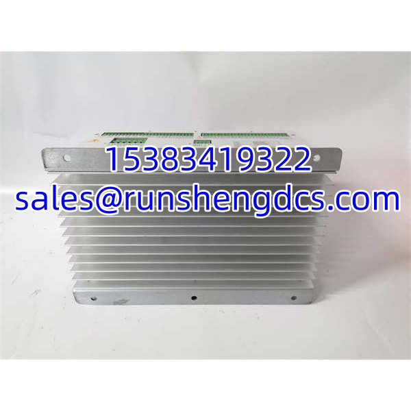
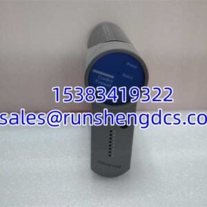
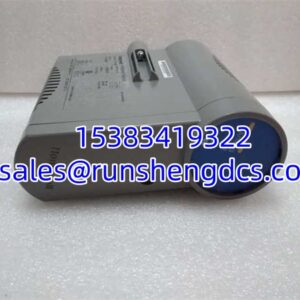
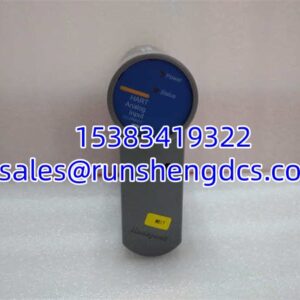
BASLER ELECTRIC DECS-200-2L
Application Scenarios
- Synchronous generator AVR replacement — Direct replacement for failed or degraded units in industrial, marine, or utility generator sets.
- Excitation system retrofit — Upgrading legacy analog AVR systems to digital excitation control with Modbus integration.
- Redundant excitation systems — Dual configurations where bumpless transfer and redundancy are required.
- Spare parts inventory — Keeping a pre-configured -2L spare to minimize generator downtime during exciter faults.
FAQ
Digital. It is a microprocessor-based excitation control system with programmable parameters, event recording, and communication interfaces.
2. What is the maximum exciter output?
Up to 125 Vdc at 15 A, depending on the specific configuration and cooling conditions.
3. Can it communicate with a DCS or SCADA?
Yes. It supports Modbus RTU over RS-485 for remote monitoring, setpoint adjustment, and alarm reporting.
Both belong to the family. The suffix indicates different configuration options (I/O, supply voltage, features). Always match the exact model and configuration to the existing installation.
5. Can I configure it without BESTCOMS software?
Basic operation is possible via the front-panel HMI, but BESTCOMS is recommended for full parameter access, stability tuning, and configuration backup.
6. Does it support redundant operation?
Yes. Two units can be configured for parallel redundancy with automatic tracking and bumpless transfer.
Yes, if your site uses -based excitation systems. A pre-configured, tested spare can significantly reduce generator outage time.