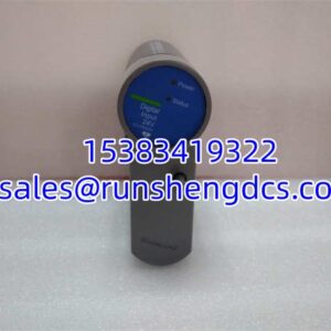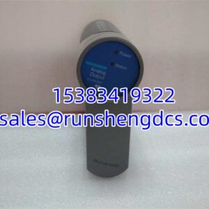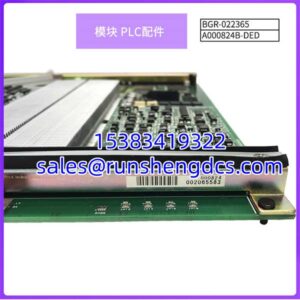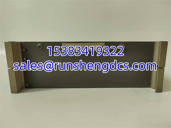

Description
Key Technical Specifications
| Parameter | Specification |
|---|---|
| Product Type | Mixed Analog I/O + PLC Function Block |
| Model | PPA322B |
| Part Numbers | HIEE300016R2 / HIEE400235R1 |
| Supply Voltage | 24 Vdc (18–32 V range) |
| Analog Inputs | 8 channels: 0–20 mA / 4–20 mA / ±10 V (software-selectable) |
| Analog Outputs | 4 channels: 0–20 mA / 4–20 mA / 0–10 V |
| Resolution | 12-bit ADC / 12-bit DAC |
| Isolation | 3 kV (channel-to-bus) |
| Communication | Ethernet/IP, Modbus TCP, PROFIBUS DP, HART |
| Operating Temperature | -25°C to +70°C |
| Mounting | 35 mm DIN rail |
| Dimensions | 200 × 120 × 45 mm |
| Weight | ≈1 kg |
| Protection Rating | IP20 (front face) |
Product Introduction
Traditional signal chains for process variables often stack three layers of hardware — a transmitter pushing 4–20 mA into an isolation barrier, then into a PLC analog card, then through a serial gateway up to the DCS. Three devices, three protocols, three failure points. The PPA322B collapses that chain into one module. It mounts on a DIN rail, accepts sensor signals directly on its AI channels, drives actuators from its AO channels, and pushes engineering-unit data to the host system over Ethernet or PROFIBUS.
The module’s 12-bit resolution delivers 0.1% AI accuracy, and the 3 kV isolation barrier lets it sit on the same rack as VFDs without common-mode noise corrupting the readings. Built-in HART master capability reads up to 15 valve positioners in roughly 1 second, pulling diagnostic data (stiction, membrane aging) without a handheld communicator. Front-panel LEDs show Run, Error, and Comm status — a glance from across the panel tells you whether you have a wiring break or a stuck valve.
QA/QC Transparency SOP
- Intake & Origin Verification: Confirm the model marking reads PPA322B and the part number matches HIEE300016R2 or HIEE400235R1. Inspect the DIN-rail clip for deformation, check terminal screws for stripping, and look for corrosion or burn marks on the PCB edge connector.
- Live Functional Testing: Power the module from a regulated 24 Vdc bench supply (set within the 18–32 V window). Verify the Run LED illuminates and the module enumerates on the Ethernet or PROFIBUS bus using a network scanner or PLC project download.
- Electrical Parameter Tests: Using a process calibrator (e.g., Fluke 724 or equivalent), inject known current/voltage signals into each AI channel and verify the digital readback matches within the 12-bit resolution spec. Drive each AO channel and measure the output with a multimeter to confirm linearity across the 0–20 mA / 4–20 mA / 0–10 V range. Perform a hi-pot test across the 3 kV isolation barrier if the unit is designated for isolated service.
- Firmware/Config Verification: Connect via the configuration tool (ABB Control Builder or equivalent) and read the firmware revision. Back up any existing project or configuration block. Confirm HART communication by polling a connected HART device or simulator.
- Final QC & Anti-Static Packaging: Clear site-specific configuration data (unless the buyer requests it retained). Pack in an anti-static bag with foam padding, and ship in a rigid carton to prevent DIN-rail clip damage in transit.
Field Engineer Gotchas
- HIEE300016R2 vs. HIEE400235R1 — Know Your Revision: These two part numbers are associated with the same PPA322B model family, but they may represent different hardware revisions or production batches. A firmware version that runs on one may not flash cleanly onto the other. Pull the old module, photograph the label, and match both the part number and the firmware rev before ordering a replacement.
- 3 kV Isolation Is Channel-to-Bus, Not Channel-to-Channel: The 3 kV rating isolates the field side from the bus/backplane. It does not guarantee galvanic isolation between individual AI channels. If you’re mixing grounded and floating sensor loops on the same module, verify that your signal references won’t create ground loops through the common bus.
- DIN Rail Heat Dissipation at 70°C: The +70°C upper operating limit is achievable, but only with adequate airflow around the module. Cramming it between two heat-generating VFDs in a sealed enclosure will push the internal temperature past spec. Leave at least one module-width gap on each side for convection.
- HART Polling Loads the Bus: The built-in HART master can read 15 devices in about 1 second, but that’s a burst. If your PLC scan time is faster than the HART polling cycle, the process variables will appear stale between updates. Size your HART polling interval to match the slowest control loop that depends on that data.
- AO Drive Capacity: The analog outputs can source up to 20 mA into a 1 kΩ load. If you’re driving an old pneumatic positioner with a high-impedance input, you may need an external amplifier. Don’t assume “4–20 mA out” means it’ll drive anything — check the load impedance.
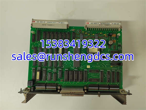
ABB PPA322B HIEE300016R2 HIEE400235R1
Application Scenarios
- Chemical Reactor Temperature & Pressure Control: The PPA322B reads temperature and pressure via its AI channels, outputs 4–20 mA to a steam control valve via AO, uses HART to read back valve position, and pushes real-time trend data to the DCS over Ethernet/IP.
- District Heating Substation: Eight AI channels connect to Pt100 transmitters monitoring supply and return temperatures across the heat exchanger. Four AO channels modulate the primary-side control valves. Modbus TCP links the module to a PLC for heat-metering calculations.
- Food & Beverage Pasteurization Line: The ±10 V differential inputs handle pressure transducer signals for the pasteurization loop. AO channels output 0–10 V to a variable-frequency screw pump drive. The IP20-rated enclosure mounts directly outside the washdown zone.
Field Case (anonymized): A chemical plant’s reactor cooling loop experienced intermittent high-temperature alarms. The operations team replaced the temperature transmitter twice. Each time, the alarm returned within 48 hours. During a third investigation, the instrument tech discovered that the PPA322B’s AI channel was configured for a 0–20 mA range, but the transmitter was outputting 4–20 mA. The 4 mA “live zero” offset was being interpreted as a valid reading, and when the transmitter’s output drifted slightly below 4 mA during a cold startup, the module read it as a negative temperature — triggering a sensor-fault alarm. Reconfiguring the channel to 4–20 mA in the module’s parameter set resolved the issue permanently. Lesson: always verify the AI range parameter matches the field device output type.
FAQ
A: Yes. The module has embedded PLC function blocks, so you can write basic logic (PID loops, comparators, timers) directly in the module using ABB Control Builder or the compatible engineering tool. It can operate independently on the process side while still uploading data when a host system is available.
Q: What’s the difference between HIEE300016R2 and HIEE400235R1?
A: Both part numbers are associated with the module family. They likely represent different production batches, hardware revisions, or order configurations. The core functionality is the same, but firmware compatibility and minor hardware details may differ. Always cross-check the exact part number and firmware revision on your existing unit before ordering a replacement.
Q: Does this module support FOUNDATION Fieldbus?
A: Not natively. The supports HART, Ethernet/IP, Modbus TCP, and PROFIBUS DP. If you need FOUNDATION Fieldbus H1, you would need an external gateway module (such as ABB’s CI910F or equivalent) connected via the bus interface.
Q: Can I mix 4–20 mA and ±10 V inputs on the same module?
A: Yes. Each AI channel is independently configurable via software. You can set channels 1–4 for current input and channels 5–8 for voltage input, or any combination. The 12-bit ADC handles both signal types at the same resolution.
Q: Is the 3 kV isolation sufficient for use in a VFD panel?
A: The 3 kV channel-to-bus isolation is designed to handle the common-mode noise typical of VFD environments. However, proper installation practices still apply — use shielded cables, ground the shield at one end only, and keep analog signal wiring separated from power cables by at least 200 mm where possible.
Q: What happens if I lose communication with the DCS?
A: The module continues to execute its embedded logic and maintain its AO outputs at their last commanded values (or a user-configured fail-safe position). The Run LED stays lit, and the Error LED will indicate a communication fault. Once the bus recovers, the module resumes data exchange automatically.