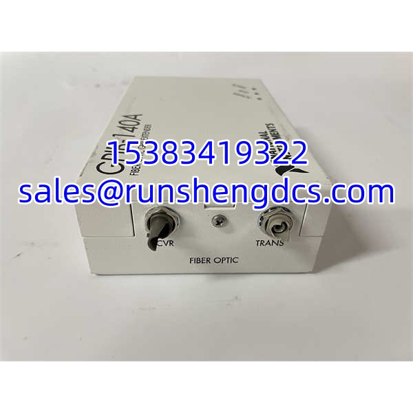

Description
Key Technical Specifications
| Parameter | Value |
|---|---|
| Product Model | GPIB-140A |
| Manufacturer | National Instruments (NI) |
| Device Type | Fiber-optic GPIB / IEEE 488 bus extender |
| Compatible Partners | GPIB-140A or GPIB-140B |
| Incompatible Partners | GPIB-140, GPIB-140/2, GPIB-140A/2 |
| Max Fiber Distance | Up to 1 km |
| Fiber Type | Multimode fiber, 62.5/125 µm |
| Optical Connectors | ST-style, duplex |
| Operating Wavelength | 850 nm |
| Fiber Attenuation | ~3.0 dB/km (public manual) |
| Optical Transceivers | HFBR1414 transmitter / HFBR2416 receiver, or equivalent |
| GPIB Standard | IEEE 488.1, IEEE 488.2 |
| HS488 Support | Yes, up to ~2.8 MB/s over the extension |
| Topology | Point-to-point; multiple pairs may be cascaded or star-connected |
| Device Loading per Extension | Up to 13 additional devices; 28 total including extenders |
| GPIB Interface Load | Two standard loads, AC and DC |
| GPIB Connector | 24-pin IEEE 488 microribbon / Champ type |
| GPIB Signal Levels | Negative-logic TTL |
| Power Supply | 100-120 VAC or 220-240 VAC, 50/60 Hz |
| Current Draw | ~120 mA at 100-120 VAC; ~80 mA at 220-240 VAC |
| Fuse | 300 mA UL/CSA approved or 500 mA IEC approved |
| Operating Temperature | 0 °C to 40 °C |
| Storage Temperature | -20 °C to 70 °C |
| Humidity | 10% to 90% non-condensing |
| Enclosure | All-metal chassis, ~0.25 kg |
| Safety Standards | IEC/EN/UL/CSA 60950-1 (as listed in NI manual) |
Product Introduction
A GPIB bus is not designed to leave the bench. IEEE 488 limits a single contiguous bus to 20 m total cable length, 2 m average device separation, and 15 device loads. The NI GPIB-140A exists to break those limits without replacing instruments, rewriting test scripts, or inserting protocol gateways.
The GPIB-140A is a functionally transparent fiber-optic GPIB extender. Installed in pairs, one unit sits at the local GPIB segment and the other at the remote segment. Each unit terminates a standard 24-pin GPIB bus, converts the parallel handshake and data signals into a serial optical stream, and reconstructs them on the far end. To the controller and instruments, the two segments still appear as one bus. Addresses, talk/listen roles, SRQ, REN, and parallel poll behavior remain logically unchanged.
This is not a GPIB-to-Ethernet converter, not a USB-GPIB adapter, and not a GPIB controller. It does not add IP connectivity. It extends the physical layer of an existing GPIB system over multimode fiber so that remote instruments can be integrated without moving the controller rack.
QA/QC Transparency SOP
- Identity & Compatibility Check — Confirm model on both units. Verify that both ends are or GPIB-140B. Reject any /2 or GPIB-140/2 pairing, as the fiber protocol is incompatible.
- GPIB Port Inspection — Inspect both 24-pin GPIB connectors for bent pins, missing shells, or damaged latches. Verify continuity and pin seating with a known-good GPIB cable.
- Optical Link Test — Connect 62.5/125 µm multimode fiber with ST connectors. Verify link establishment, optical transmit/receive LEDs, and stable synchronization. Measure optical power if test equipment is available.
- Functional GPIB Verification — Connect a GPIB controller and at least one instrument on each side. Run address polling, device clear, trigger, read/write, and SRQ tests. Confirm that remote instruments respond identically to local instruments.
- HS488 & Parallel Poll Check — If the local system supports HS488, verify extended throughput. Test immediate and latched parallel poll response modes if required by the application.
- Final Documentation — Record serial numbers, firmware/revision if readable, fiber type, link distance, test results, and condition. Package with ST dust caps, GPIB connector protectors, and ESD-safe materials.
Field Engineer Gotchas
- Pairing is strict. works with or GPIB-140B. It will not link to GPIB-140, GPIB-140/2, or /2.
- It is point-to-point, not multidrop over fiber. You cannot tap additional instruments off the fiber run. Additional devices must be added on the local or remote GPIB segment.
- Fiber must be multimode 62.5/125 µm. Single-mode fiber or incorrect ST patch cables can prevent link acquisition even when both units power up normally.
- Device loading still applies per segment. Each extension supports up to 28 total devices including the extenders, with up to 13 additional devices per extension.
- HS488 requires system-wide support. The extender can carry HS488, but all participating GPIB devices and the controller must also support it for higher throughput.
- No software change is required in normal use. The extender is functionally transparent, but parallel poll behavior may require configuration depending on the application.

NI GPIB-140A
Application Scenarios
- Remote ATE rack extension. A legacy GPIB-based test system remains in a control room while instruments are relocated to a shielded test chamber 200 m away. The pair carries the bus over multimode fiber without modifying test software.
- EMI-sensitive measurement environment. In a high-noise power electronics lab, copper GPIB cables pick up switching noise. Fiber isolation eliminates ground loops and conducted interference between the controller and instruments.
- Distributed calibration station. A central GPIB controller manages multimeters, sources, and environmental chambers across two rooms. Two units create a single logical bus across the fiber link.
- Legacy system preservation. A production test cell relies on GPIB instruments that cannot be replaced. The extends the bus to a new equipment layout while keeping the existing NI-488.2 driver stack and LabVIEW code unchanged.
FAQ
Yes. GPIB-140B can communicate with . It cannot communicate with , /2, or /2.
Does it require driver changes?
No. The extender is functionally transparent. Existing NI-488.2, VISA, or LabVIEW GPIB applications typically work without modification.
What fiber cable is required?
62.5/125 µm multimode fiber with ST-style connectors, duplex configuration.
How many devices can it support?
Up to 28 total devices including the extenders, with up to 13 additional devices per extension segment.
Is it still supported by NI?
The is a legacy product. NI has since released newer extenders such as the GPIB-140B. For production-critical systems, verify current support status with NI and maintain tested spare pairs on site.
Can I cascade multiple extenders?
Multiple point-to-point extension pairs can be arranged in series or star patterns, but each fiber link remains a separate extender pair. Plan GPIB addressing, loading, and timing carefully.
Does it isolate ground loops?
Yes. The fiber link provides electrical isolation between the local and remote GPIB segments, which helps eliminate ground loops and reduces susceptibility to EMI.