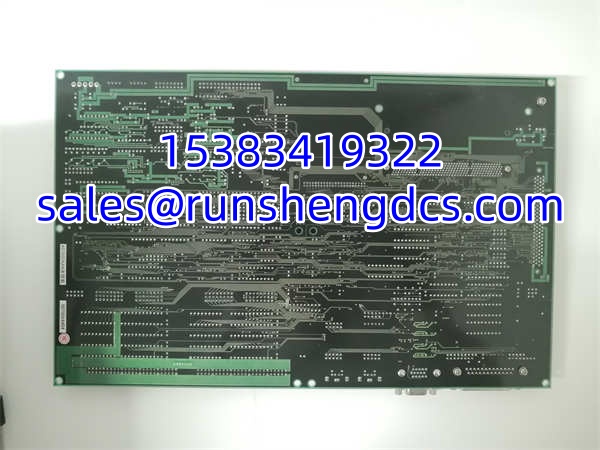

Description
Key Technical Specifications
| Parameter | Specification |
|---|---|
| Manufacturer | KOKUSAI (Kokusai Electric), Japan |
| Model | CXP-544A KOMS-A2 |
| Product Type | Industrial Embedded CPU Board / Data Acquisition & Control Module |
| Processor | Intel Pentium M, 1.6 GHz |
| Memory | 512 MB DDR |
| Storage | 2 GB SSD |
| Operating System | Windows XP Embedded |
| Communication Interfaces | Ethernet (10/100 Mbps), RS-232, RS-485, USB |
| I/O Channels | Multi-channel analog inputs (for sensor signals), digital I/O (exact count varies by configuration) |
| Input Signal Types | Analog (temperature, pressure, flow, vibration sensors), digital discrete signals |
| Data Acquisition | High-resolution ADC with noise filtering and signal conditioning |
| Protection Level | IP65 (enclosure), conformal-coated PCB for moisture/dust resistance |
| Operating Temperature | 0°C to +50°C |
| Storage Temperature | -20°C to +60°C |
| Humidity Range | 5% to 95% (non-condensing) |
| Dimensions | 230 mm × 165 mm × 65 mm |
| Weight | 2.0 kg |
| Power Supply | DC 24V (±10%), typical power consumption ≤10W |
| Cooling | Fanless design (passive cooling) |
| Country of Origin | Japan (MADE IN JAPAN marked on PCB) |
| Product Status | Legacy/discontinued |
| Warranty (distributor) | Typically 12 months from acceptance |
Product Introduction
The KOKUSAI CXP-544A KOMS-A2 is a compact, fanless industrial embedded controller and data acquisition board manufactured by Kokusai Electric, a Japanese company founded in 1946 that specializes in automation and control solutions for industrial, automotive, and healthcare applications. The module belongs to the KOMS series industrial control platform and is primarily designed for semiconductor manufacturing equipment — particularly temperature control systems in chemical vapor deposition (CVD) and physical vapor deposition (PVD) processes — but its flexible architecture also makes it suitable for general-purpose industrial automation, data acquisition, and machine control tasks.
At its core, the CXP-544A KOMS-A2 is built around an Intel Pentium M processor running at 1.6 GHz, paired with 512 MB of RAM and 2 GB of SSD storage, running Windows XP Embedded as its operating system. This combination provides sufficient processing power for real-time control algorithms, data logging, and communication with host systems. The fanless design eliminates a common point of mechanical failure and reduces noise, making it ideal for cleanroom environments in semiconductor fabs where particle contamination must be minimized.
The module’s primary strength lies in its multi-channel data acquisition capability. It features multiple analog input channels that can accept signals from a wide variety of industrial sensors — including temperature sensors (thermocouples, RTDs), pressure transducers, flow meters, vibration sensors, and position encoders. The onboard ADC provides high-resolution digitization of these analog signals, with built-in noise filtering and signal conditioning to ensure measurement accuracy in electrically noisy industrial environments. The module also supports digital I/O channels for discrete control signals, allowing it to drive relays, solenoid valves, and indicator lamps directly.
For system integration, the CXP-544A KOMS-A2 provides a comprehensive set of communication interfaces: Ethernet (10/100 Mbps) for network connectivity, RS-485 for serial communication with PLCs and other industrial devices, RS-232 for legacy equipment interfacing, and USB for peripheral connections or firmware updates. These interfaces support standard industrial protocols, enabling the module to exchange data with DCS systems, SCADA platforms, and host computers for remote monitoring and control.
The module is housed in a rugged IP65-rated enclosure measuring 230 mm × 165 mm × 65 mm and weighing 2.0 kg. The IP65 rating means it is dust-tight and protected against low-pressure water jets from any direction, making it suitable for installation in harsh industrial environments. The internal PCB is conformal-coated for additional protection against moisture, dust, and chemical vapors. It operates on a DC 24V power supply (±10%) with typical power consumption of no more than 10 watts, and its fanless passive cooling design ensures reliable operation in ambient temperatures from 0°C to 50°C.
In semiconductor manufacturing applications, the CXP-544A KOMS-A2 is commonly used as the temperature control brain for CVD and PVD process chambers. It reads temperature feedback from multiple thermocouples embedded in the chamber walls and heater blocks, runs PID control algorithms to maintain precise temperature profiles during deposition cycles, and drives heater power controllers and cooling valve actuators to keep the process within specification. The module’s high-resolution ADC and fast processing ensure that temperature deviations are detected and corrected quickly, which is critical for achieving uniform film deposition and high yield rates.
As a legacy product, the CXP-544A KOMS-A2 is no longer in production by KOKUSAI. It is available through authorized surplus distributors and industrial automation spare parts suppliers, typically as new old stock (NOS) or factory-refurbished units. When sourcing replacements, always verify the module’s firmware version and ensure it is compatible with your existing system configuration.
QA/QC Transparency SOP
- Intake & Visual Inspection: Each module is inspected for physical damage — cracked or warped enclosure, damaged communication ports (Ethernet, RS-485, USB), corroded I/O terminal blocks, burnt or discolored components on the PCB (especially around the power supply section and processor), or signs of moisture ingress (white residue on PCB). Units with charred components, swollen capacitors, or damaged connectors are rejected.
- Power-On Self-Test (POST): The module is powered on with a regulated DC 24V supply. We verify that the module boots successfully into Windows XP Embedded, that the processor and memory are recognized correctly, and that the SSD is accessible. We check for any BIOS error codes or boot failures. Modules that fail to POST or show memory/storage errors are rejected.
- Communication Interface Verification: Each communication interface (Ethernet, RS-232, RS-485, USB) is tested for functionality. For Ethernet, we verify link establishment and data transmission at 10/100 Mbps. For RS-485 and RS-232, we perform loopback tests and verify baud rate accuracy. For USB, we verify that peripherals (keyboard, mouse, flash drive) are recognized. Any interface that fails to establish communication or shows data corruption is grounds for rejection.
- Analog Input Channel Calibration Check: Each analog input channel is tested by applying a known reference voltage (e.g., 0V, 2.5V, 5V) and verifying that the digitized reading matches the expected value within the module’s specified accuracy tolerance. We check for channel-to-channel crosstalk by applying signals to one channel while monitoring adjacent channels. Channels that show significant offset, gain error, or crosstalk are grounds for rejection.
- Digital I/O Channel Verification: Each digital input channel is tested by applying a 24VDC signal and verifying that the module correctly registers the input state (ON/OFF). Each digital output channel is tested by commanding the output ON and OFF and measuring the voltage at the output terminal. We verify that outputs switch cleanly and can source/sink the rated current. Channels that fail to register or show intermittent behavior are grounds for rejection.
- Temperature Stress Test (sample basis): For each batch of modules, a sample unit is placed in a temperature chamber and cycled between 0°C and 50°C for 10 cycles while operating. After the temperature cycling, the module is retested for boot, communication, and I/O functionality. Any module that fails post-cycling tests results in rejection of the entire batch.
- Final QC & Anti-Static Packaging: After passing all tests, the module is placed in an anti-static bag with desiccant and shipped in a rigid box with foam inserts to protect the enclosure and connectors. A test report with channel-by-channel verification is included.
Field Engineer Gotchas
- Windows XP Embedded end-of-life implications: The runs Windows XP Embedded, which has been end-of-life since 2019. This means no security patches or official Microsoft support. If the module is connected to a corporate network, ensure it is isolated behind a firewall or VLAN to prevent exposure to network-based threats. For new installations, consider whether a modern replacement platform would be more appropriate.
- Analog input range matching: The ‘s analog input channels have specific voltage or current input ranges (e.g., 0-5V, 0-10V, 4-20mA). Before connecting sensors, verify that the sensor’s output signal matches the module’s configured input range. Connecting a sensor with an incompatible output range (e.g., a 0-10V sensor to a 0-5V input) will result in inaccurate readings or potential damage to the input circuitry. Use signal conditioners or range-matching resistors if needed.
- RS-485 termination and polarity: When connecting the to an RS-485 network, ensure that the bus is properly terminated with a 120-ohm resistor at each end of the bus to prevent signal reflections. Also verify the A/B polarity of the RS-485 wiring — swapping A and B will prevent communication. Use shielded twisted-pair cable for RS-485 runs and terminate the shield at one end only to avoid ground loops.
- Fanless design thermal considerations: While the fanless design is a reliability advantage, it also means the module relies entirely on passive cooling through its enclosure. Ensure adequate airflow around the module and avoid installing it in enclosed spaces without ventilation. The module’s operating temperature range is 0°C to 50°C — if ambient temperatures exceed 50°C, the module may overheat and shut down. In high-temperature environments, consider adding external cooling (e.g., an enclosure air conditioner or heat exchanger).
- IP65 rating and cable gland integrity: The IP65 rating applies to the enclosure itself, but the overall ingress protection depends on proper installation of cable glands and connectors. Ensure all cable entries are sealed with appropriate IP-rated cable glands, and that communication port covers are installed when ports are not in use. A single unsealed cable entry can compromise the entire enclosure’s protection rating.
- SSD lifespan in continuous operation: The uses a 2 GB SSD for storage. In continuous operation with frequent data logging, the SSD’s write endurance may become a concern over time. If the module is used for high-frequency data logging, consider implementing a circular buffer or rotating log files to minimize write wear on the SSD. Monitor the SSD’s health status if the operating system provides S.M.A.R.T. data.
- Replacement compatibility: If you are replacing a failed module, verify that the replacement has the same firmware version and I/O configuration. Different revisions of the module may have different analog input ranges, digital I/O counts, or communication protocol support. Consult the module’s nameplate and the original system documentation to ensure compatibility.
- Semiconductor fab cleanroom compatibility: If the module is installed in a semiconductor fab cleanroom, verify that the enclosure material and any labels or markings are compatible with cleanroom cleaning protocols (e.g., resistant to isopropyl alcohol, hydrogen peroxide vapor). Some enclosure materials may degrade or off-gas in cleanroom environments, potentially contaminating the process.
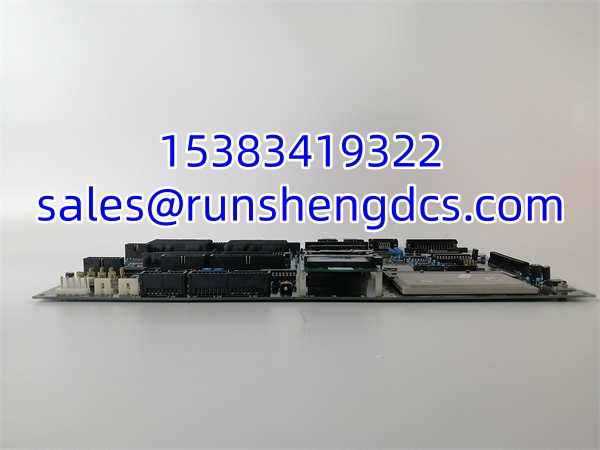
KOKUSAI CXP-544A KOMS-A2
Application Scenarios
- Semiconductor CVD chamber temperature control: In a semiconductor fabrication facility, the is installed inside the control cabinet of a chemical vapor deposition (CVD) system. The module’s analog input channels are connected to multiple K-type thermocouples embedded in the CVD chamber walls, heater blocks, and gas distribution plate. The module runs a multi-zone PID control algorithm that reads temperature feedback from each thermocouple, compares it to the recipe-specified temperature profile, and adjusts the power output to each heater zone via solid-state relays. The module’s high-resolution ADC (16-bit or better) ensures temperature measurement accuracy of ±0.5°C, which is critical for achieving uniform film thickness across the wafer. The Ethernet interface connects the module to the fab’s host computer, which downloads process recipes and logs temperature data for SPC (statistical process control) analysis. The fanless design prevents particle generation inside the cleanroom.
- PVD process monitoring and control: In a physical vapor deposition (PVD) system, the monitors and controls multiple process parameters simultaneously. Analog inputs read pressure from the chamber vacuum gauge, flow rates from mass flow controllers (MFCs) for argon and nitrogen process gases, and temperature from the substrate heater. Digital outputs control the RF power supply enable, gas valve solenoids, and substrate rotation motor. The module’s RS-485 interface connects to the MFCs for setpoint control and flow readback. The module logs all process data to its onboard SSD and transmits real-time status to the fab’s SCADA system via Ethernet. If any parameter deviates from the recipe specification (e.g., chamber pressure rises above the setpoint due to a gas leak), the module triggers an alarm and can automatically abort the process to prevent defective wafers.
- Industrial machine vision and quality inspection: In an automotive parts manufacturing line, the is used as the controller for a machine vision inspection station. The module’s USB interface connects to a CCD camera that captures images of machined components. The Pentium M processor runs image processing algorithms to detect surface defects, dimensional deviations, and missing features. Digital outputs trigger a pneumatic reject actuator when a defective part is detected. The Ethernet interface sends inspection results and defect images to a central quality database. The module’s compact size and fanless design allow it to be mounted directly on the production line without requiring a separate control cabinet.
- Remote data acquisition for oil and gas pipelines: In an oil and gas pipeline monitoring application, multiple modules are deployed at remote pipeline valve stations. Each module reads pressure and temperature from pipeline sensors via its analog inputs, monitors valve position feedback via digital inputs, and controls valve actuators via digital outputs. The modules communicate with the central control room via Ethernet over fiber-optic links. The IP65-rated enclosure and wide operating temperature range allow the modules to operate reliably in outdoor installations exposed to rain, dust, and temperature extremes. The fanless design eliminates a maintenance item in remote locations where regular servicing is difficult.
FAQ
A: Some sources suggest that the may support NI software tools for configuration and data analysis. However, this is not confirmed by official KOKUSAI documentation. If LabVIEW integration is required for your application, verify with the supplier whether the specific module revision includes NI-DAQmx drivers or whether a custom driver is needed. In many cases, the module’s standard communication interfaces (Ethernet, RS-485) can be used to exchange data with LabVIEW via TCP/IP or serial protocols without requiring NI-DAQmx.
A: The is primarily designed for temperature control, data acquisition, and general-purpose industrial automation. While it has digital I/O channels that could be used for basic motion control (e.g., start/stop commands, limit switch monitoring), it does not have dedicated motion control features such as pulse/direction outputs or encoder inputs. For complex motion control applications, consider using a dedicated motion controller or a PLC with motion control capabilities.
Q: What is the maximum sampling rate for the analog input channels?
A: The exact sampling rate depends on the specific hardware revision and the number of channels being sampled simultaneously. Typical industrial data acquisition modules of this class support sampling rates in the range of 100 Hz to 1 kHz per channel. For high-speed applications requiring faster sampling, verify the specific module revision’s datasheet or consult the supplier. If higher sampling rates are needed, consider using a dedicated high-speed DAQ module.
Q: Can the operating system be upgraded from Windows XP Embedded?
A: The ‘s hardware (Intel Pentium M processor, 512 MB RAM) is relatively old and may not support modern operating systems such as Windows 10 IoT or Linux distributions with current kernel requirements. If an OS upgrade is required for security or compatibility reasons, verify with the supplier whether a compatible OS image is available. In many cases, it may be more practical to replace the module with a modern industrial PC that supports current operating systems.
A: The analog input range configuration method depends on the specific hardware revision. Some revisions may use hardware jumpers or DIP switches on the PCB to select the input range (e.g., 0-5V, 0-10V, 4-20mA). Others may allow software configuration through the module’s control software or a configuration utility. Consult the module’s hardware manual or contact the supplier for the specific configuration procedure for your revision.
A: Since the is no longer in production by KOKUSAI, it is available through authorized surplus distributors and industrial automation spare parts suppliers. Reputable suppliers include Askplc Limited, Xiamen Xiongba E-Commerce, Shenzhen Changxin Automation, and other specialized industrial surplus dealers. Always verify the supplier’s reputation, warranty terms (typically 12 months), and return policy before purchasing. Request a test report and photos of the actual module before committing to a purchase.