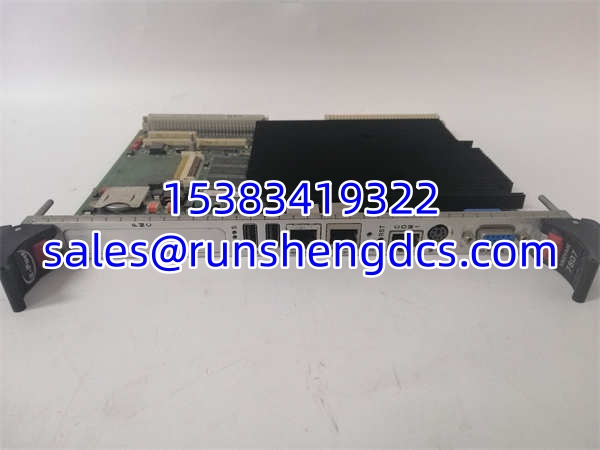

Description
Key Technical Specifications
| Parameter | Specification |
|---|---|
| Model | VMIVME-7807-411001 |
| Alternate Order Number | 350-007807-411001 |
| Manufacturer | GE Fanuc Embedded Systems / GE Intelligent Platforms |
| Product Family | VMIVME-7807 / VME-7807RC 6U VMEbus SBC |
| Form Factor | 6U VME64x (233 × 160 mm), single-slot |
| Processor | Intel Pentium M — 1.1 GHz (1 MB L2), 1.6 GHz (1 MB L2), or 1.8 GHz (2 MB L2) |
| Chipset | Intel 855GME with 6300ESB I/O Controller Hub |
| System Bus | 400 MHz |
| System Memory | Up to 1.5 GB DDR SDRAM (512 MB soldered + 1 GB SODIMM), optional ECC support |
| Boot Storage | Up to 1 GB bootable CompactFlash on secondary IDE (ordering option dependent) |
| Nonvolatile SRAM | 32 KB battery-backed |
| Ethernet – 10/100 | 1× Intel 82551ER, front panel RJ-45 |
| Ethernet – Gigabit | Dual Intel 82546EB — 1× front panel RJ-45 (10/100/1000BaseT), 1× routed to P2 rear I/O; both can be routed to optional P0 connector for VITA 31.1 support |
| Serial Ports | 4× asynchronous 16550-compatible (COM1 front panel RJ-45; COM2–COM4 on P2 rear I/O), RS-232/422 configurable, up to 115 Kbaud, 16-byte FIFO |
| USB | 4× USB 2.0 (2 front panel, 2 rear I/O via P2), 480 Mbps |
| Video | Integrated SVGA (front panel) + DVI-D (rear I/O), dual-head capability |
| SATA | Serial ATA via P2 rear I/O |
| IDE | Secondary IDE for CompactFlash |
| PMC Expansion | 1× PCI-X 66 MHz PMC slot (IEEE 1386.1, 5V) |
| VMEbus Interface | Tundra Universe II PCI-to-VME bridge; supports A32/A24/D32/D08(EO)/MBLT64/BLT32; system controller or peripheral role |
| Timers | 2× 16-bit + 2× 32-bit software-programmable timers |
| Watchdog | Software-enabled watchdog with configurable timeout → reset, NMI, or SYSFAIL |
| Power Requirement | +5 VDC only; typical <12 A at 1.1 GHz / 1 GB RAM (~60 W max) |
| Cooling | Passive heatsink; requires forced air cooling, minimum 450 LFM airflow |
| Operating Temperature | 0°C to 60°C |
| Operating Systems | Windows XP, Windows 2000, VxWorks, QNX, LynxOS, Linux |
| BIOS | Reprogrammable flash for system and video BIOS; battery-backed CMOS configuration |
| Standards Compliance | VME64x, VITA 1.1-1994, CE, RoHS |
| Typical Applications | Industrial process control, factory automation, aerospace/military embedded systems, automatic test equipment (ATE), radar systems, turbine control, legacy VME system life-extension |
Product Introduction
The VMIVME-7807-411001 is a 6U VMEbus single board computer from GE Fanuc Embedded Systems (now GE Intelligent Platforms). This is not an Ethernet switch — despite what some third-party listings incorrectly claim. It is a full-featured Pentium M-based VME processor card designed to replace legacy 68k or older Pentium-based VME CPU modules in industrial, aerospace, and military control racks.
Why this board matters in the field:
Many critical industrial and defense systems built in the 1990s and early 2000s rely on VME64x backplanes with proprietary I/O cards, terminal blocks, and safety relays that are still fully functional. Replacing the entire rack with a modern PLC or PC-based system would require complete rewiring, re-certification (especially in aerospace and military applications), and potentially months of downtime. The VMIVME-7807 solves this problem by dropping directly into an existing VME slot — preserving all field-proven I/O wiring and peripheral cards — while providing a modern Pentium M processor capable of running contemporary real-time operating systems, edge analytics, or remote diagnostic software.
What the ordering code “-411001” means:
The VMIVME-7807 uses a suffix-based ordering system. Based on the official ordering options documentation:
- A (Processor): 2 = 1.1 GHz Pentium M (1 MB L2), 3 = 1.6 GHz Pentium M (1 MB L2), 4 = 1.8 GHz Pentium M (2 MB L2)
- B (DDR SDRAM): 1 = 512 MB, 2 = 1 GB, 3 = 1.5 GB
- C (CompactFlash): 0 = none, 1 = 128 MB, 2 = 256 MB, 3 = 512 MB, 4 = 1 GB
- D (P0 Connector): 0 = no P0, 1 = P0 installed (with Gigabit Ethernet and VITA 31.1 support)
- E (ECC): 0 = no ECC, 1 = with ECC
- F (Special): 0 = VME standard, 1 = 1101.10 front panel
The -411001 suffix decodes as: 4 = 1.8 GHz Pentium M (2 MB L2), 1 = 512 MB DDR SDRAM, 1 = 128 MB CompactFlash, 0 = no P0 connector, 0 = no ECC, 1 = special front panel. Always verify the exact configuration of any surplus unit against this decoding before purchasing — processor speed, memory, and CompactFlash capacity vary by suffix.
Architecture overview:
The VMIVME-7807 is built around the Intel 855GME chipset with the 6300ESB I/O Controller Hub. This advanced hub architecture separates high-bandwidth I/O from the PCI bus, reducing bottlenecks and improving overall system throughput compared to earlier VME SBC designs. The Tundra Universe II PCI-to-VME bridge provides the VMEbus interface, supporting full VME64x protocols including MBLT64 and BLT32 transfers.
Key architectural features:
- Dual-port DDR SDRAM: The SDRAM is dual-ported to the VMEbus, allowing other VME modules to directly access the SBC’s memory for high-speed data exchange — critical for real-time control applications where deterministic data sharing between processor and I/O modules is required.
- Dual Gigabit Ethernet: Two Intel 82546EB Gigabit Ethernet controllers provide redundant or segregated network paths. One port is front-panel accessible; the second is routed to the P2 rear I/O connector. With the optional P0 connector, both Gigabit ports can be routed to the VME64x backplane for VITA 31.1 compliance (Gigabit Ethernet over VME backplane).
- PMC expansion slot: The single PCI-X 66 MHz PMC slot (IEEE 1386.1) allows addition of specialized mezzanine cards — MIL-STD-1553 interfaces, additional analog I/O, FPGA-based custom interfaces, or FireWire cards. Note: inserting a legacy 33 MHz/32-bit PMC card will reduce the PMC bus to 33 MHz/32-bit operation.
- Watchdog timer: Software-programmable watchdog with configurable timeout action (reset, non-maskable interrupt, or VMEbus SYSFAIL). Essential for无人值守 industrial and aerospace applications where automatic recovery from software hangs is required.
- Nonvolatile SRAM: 32 KB battery-backed SRAM retains critical configuration data, calibration constants, or event logs across power cycles.
Operating system support:
The supports a wide range of embedded and real-time operating systems:
- Windows XP / Windows 2000 — for HMI, data logging, or non-real-time supervisory applications
- VxWorks — Wind River’s hard real-time OS, widely used in aerospace and defense
- QNX — POSIX-compliant real-time OS for industrial control
- LynxOS — hard real-time OS for safety-critical applications
- Linux — various embedded Linux distributions for custom applications
Thermal management:
The board uses a passive heatsink — there are no onboard fans. Proper operation requires forced air cooling with a minimum of 450 LFM (linear feet per minute) airflow, particularly on the output side of the heatsink. This is a critical installation requirement — insufficient airflow will cause thermal throttling or shutdown of the Pentium M processor. When installing in a legacy VME chassis, verify that the chassis fans are operational and that airflow paths are not obstructed by adjacent modules.
Rear transition modules:
To access rear I/O (SATA, additional USB, serial ports COM2–COM4, DVI-D, second Gigabit Ethernet), a rear transition module (RTM) is required. Compatible RTMs include:
- VMIACC-0586 / ACC-0586RC
- VMIACC-0590 / ACC-0590RC
Troubleshooting Quick Reference
| Fault Symptom | Likely Cause | Probability | Quick Check | Fix |
|---|---|---|---|---|
| Board does not boot / no POST | Insufficient airflow causing thermal shutdown; CMOS battery depleted | ~25% | Verify chassis fans are running; measure airflow at heatsink (>450 LFM); check CMOS battery voltage | Restore proper airflow; replace CMOS battery (CR2032 or equivalent); clear CMOS and reconfigure BIOS settings. |
| VMEbus communication failure | Tundra Universe II bridge not initialized; VME slot configuration mismatch | ~20% | Verify board is in a system controller slot if acting as system controller; check VME address/data bus configuration in BIOS | Ensure correct slot assignment (system controller vs. peripheral); verify VME interrupt levels and address spaces do not conflict with other modules. |
| Ethernet port not linking | Front panel RJ-45 damaged; Intel 82551ER/82546EB driver not loaded; cable fault | ~15% | Check link LED on front panel; test with known-good cable; verify OS network driver is installed | Replace cable; reinstall network driver; if front panel port is physically damaged, route traffic through rear I/O Gigabit port via RTM. |
| CompactFlash not detected | CF card not seated; BIOS boot order incorrect; CF card failure | ~15% | Reseat CompactFlash card; enter BIOS and verify boot device order; test CF card in another system | Replace CompactFlash card if faulty; ensure BIOS is configured to boot from secondary IDE (CF). |
| PMC module not recognized | PMC card incompatibility (3.3V card in 5V slot); PCI-X bus speed mismatch | ~10% | Verify PMC card voltage rating ( PMC slot is 5V); check for physical damage to PMC connector | Use only 5V PMC cards; if using a 33 MHz/32-bit legacy PMC card, expect reduced bus speed. |
| Watchdog timeout resets | Application software not servicing watchdog; watchdog timer period too short | ~10% | Check application code for watchdog kick/refresh calls; review watchdog configuration in BIOS or driver | Increase watchdog timeout period; fix application software to properly service watchdog within timeout window. |
| Memory errors / ECC failures | SODIMM not seated; SODIMM failure; ECC mismatch in BIOS | ~5% | Reseat SODIMM; run memory diagnostic; verify ECC setting in BIOS matches installed memory type | Replace faulty SODIMM; ensure BIOS ECC setting matches memory configuration (ECC vs. non-ECC). |
| Serial port communication failure | RS-232/422 mode mismatch; FIFO overflow at high baud rates | ~5% | Verify serial mode configuration (RS-232 vs. RS-422); check baud rate settings; monitor for framing errors | Reconfigure serial port mode to match connected device; reduce baud rate if FIFO overflow is occurring; verify cable pinout. |
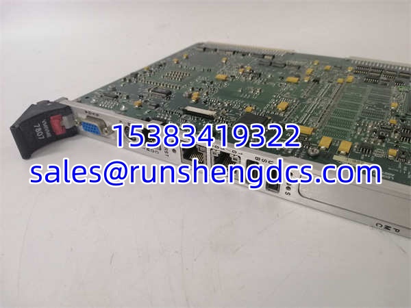
GE VMIVME-7807-411001 VMIVME-7807
Application Scenarios & Pain Points
Legacy turbine control system life-extension. A power generation facility operating a frame gas turbine with a 20-year-old VME-based control system faced obsolescence of the original Motorola 68k CPU module. Replacement parts were unavailable, and a full control system upgrade would require months of engineering and certification. The -411001 was installed as a drop-in replacement, preserving all existing I/O modules, terminal blocks, and field wiring. Pain point: the existing VME chassis had degraded fans providing only ~300 LFM airflow, causing the Pentium M to thermal-throttle under load. The fix: upgrading the chassis fans to restore >450 LFM airflow and adding an airflow deflector to direct cooling air across the ‘s heatsink. The system has operated reliably since the retrofit.
Aerospace test stand data acquisition. An aerospace test facility uses boards as system controllers in VME-based automatic test equipment (ATE) racks. Pain point: after a power outage, multiple boards failed to boot due to depleted CMOS batteries (15+ years of service). The batteries had leaked, corroding the battery holders. The fix: replacing all CMOS batteries and cleaning corroded battery contacts. As a preventive measure, the facility implemented a scheduled battery replacement program every 5 years for all boards in service. Lesson: CMOS battery replacement should be part of preventive maintenance for any installation older than 5 years.
Military radar signal processing. A naval radar system uses boards with PMC mezzanine cards for MIL-STD-1553 communication. Pain point: intermittent PMC card recognition failures were traced to vibration loosening the PMC card retention mechanism in the shipboard environment. The fix: adding a secondary mechanical retention clip to secure the PMC card and applying thread-locking compound to the PMC mounting screws. The itself was not at fault — the issue was mechanical retention of the mezzanine card in a high-vibration environment.
Industrial process control migration. A chemical processing plant migrated from an obsolete VME CPU to the while retaining existing analog and digital I/O modules. Pain point: the VMEbus memory mapping configuration in the BIOS did not match the legacy system’s address space assignments, causing I/O modules to be unreachable. The fix: carefully documenting the legacy system’s VME address map and replicating it in the BIOS configuration. This required detailed knowledge of the legacy system’s memory map — a task best performed by engineers familiar with the original system design.