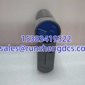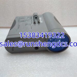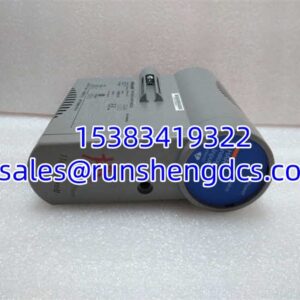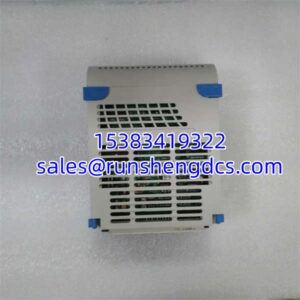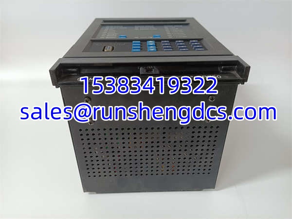

Description
Key Technical Specifications
| Parameter | Value |
|---|---|
| Model | SR 750-P1-G1-S1-HI-A20-G |
| Brand | GE Multilin |
| Series | SR750 Feeder Management Relay |
| Application | Feeder, motor, and transformer protection |
| Protection Functions | Overcurrent (50/51), ground fault (50N/51N), thermal overload (49), undervoltage/overvoltage (27/59) |
| Metering | Voltage, current, power, energy, frequency |
| Event Recording | Sequence of events (SOE) with time-stamped fault logs |
| Communication | Ethernet, serial (Modbus, DNP3 — verify per configuration) |
| Mounting | Panel / rack mount (verify with GE Multilin installation manual) |
| Operating Temperature | Verify with OEM datasheet (typical industrial range: 0°C to 55°C) |
| Standards Compliance | IEC 60255, IEEE C37 series (verify specific editions with OEM) |
Product Introduction
Medium-voltage feeder protection used to mean stacking separate relays for overcurrent, ground fault, thermal overload, and metering — each with its own wiring, CT/PT burden, and maintenance schedule. The GE SR750 platform consolidated those functions into a single chassis, and the SR 750-P1-G1-S1-HI-A20-G is one specific configuration of that platform. It sits at the feeder bay level, reading CT/PT inputs, executing protection logic, recording fault events, and communicating status upstream to a SCADA or DCS system.
The value proposition is straightforward: one device replaces multiple single-function relays, reducing panel space, wiring complexity, and spare parts inventory. The SR750 family supports configurable protection curves (IEC and IEEE/ANSI), integrated power quality metering, and time-stamped event logs that make post-fault analysis faster. For facilities running aging protection schemes on electromechanical or early solid-state relays, migrating to an SR750 configuration cuts maintenance burden and gives operators visibility into feeder health that older systems simply didn’t provide.
QA/QC Transparency SOP
For surplus or pulled modules, a responsible test sequence looks like this:
- Intake & Origin Verification. Photograph the front panel, rear terminal connections, and nameplate. Record the full model number including all suffix codes. Check for physical damage — cracked display segments, corroded terminals, or missing configuration jumpers.
- Live Functional Testing. Power up the unit on a bench supply at rated voltage. Confirm the display initializes without error codes. Load a known configuration file (or factory default) and verify that protection function menus are accessible and that metering displays respond to injected test currents/voltages via secondary injection test kit.
- Electrical Parameter Tests. Perform insulation resistance testing between input terminals and chassis ground. Verify CT/PT input circuit continuity. Check contact output operation by triggering each protection element and confirming relay pickup/dropout at expected setpoints.
- Firmware/Config Verification. Read the firmware revision from the unit’s display or communication port. Back up any stored configuration and event logs. Compare firmware version against GE Multilin’s compatibility matrix for the target application.
- Final QC & Anti-Static Packaging. Clear test configurations. Package with terminal covers installed and anti-static shielding. Include a test report documenting power-up verification, protection element spot-checks, and firmware revision.
Field Engineer Gotchas
- CT Ratio and Burden Mismatch. The expects specific CT ratios and burden values configured in software. If the field CTs don’t match the relay’s programmed ratio, your pickup settings will be wrong by a proportional factor. I’ve seen a 400:5 CT system configured as 200:5 in the relay — every protection threshold was off by 2x. Always cross-check the CT nameplate against the relay configuration before energizing.
- Communication Protocol Conflicts. The supports multiple protocols (Modbus, DNP3, etc.) but only one active protocol at a time on a given port. If a previous owner configured it for Modbus and you’re trying to talk DNP3, you’ll get nothing. Check the communication setup menu first — don’t waste time troubleshooting SCADA tags when the protocol itself is wrong.
- Configuration File Dependency. This isn’t a “plug and play” relay. It ships with factory defaults that won’t match your protection scheme. You need the correct configuration file loaded before it protects anything meaningful. Running it with factory settings on a live feeder is a good way to find out your protection doesn’t coordinate with upstream devices.
- Battery-Backed Clock Drift. The real-time clock maintains event timestamps. On surplus units that have been sitting unpowered for months, the clock battery may be depleted. Verify the clock is holding time before relying on SOE records for fault analysis — a relay with a dead clock stamps every event with the same bogus timestamp.
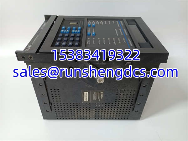
GE SR 750-P1-G1-S1-HI-A20-G
Application Scenarios
- Industrial Substation Feeder Protection. Medium-voltage switchgear feeding process areas in petrochemical plants, mining operations, or large manufacturing facilities needs coordinated overcurrent and ground fault protection. The provides ANSI/IEEE 50/51 and 50N/51N elements with configurable time-current curves.
- Large Motor Protection. High-voltage induction motors require thermal overload (ANSI 49), locked rotor, and unbalance protection. The integrates these functions with metering to track motor health over time.
- Transformer Feeder Management. Distribution transformers in industrial plants benefit from integrated overcurrent, ground fault, and temperature-based protection in a single device, reducing the relay count per transformer bay.
- Retrofit of Electromechanical Relays. Facilities replacing aging induction-disk or solid-state relays with digital protection need a platform that fits existing panel layouts and can replicate legacy protection schemes while adding metering and communications.
Anonymized Case: A pulp and paper mill had three 13.8 kV feeder breakers protected by 30-year-old electromechanical overcurrent relays with no metering or event recording. After a ground fault on one feeder took 45 minutes to diagnose (operators had no fault data — just a tripped breaker), the plant engineer spec’d units for all three feeders. The new relays provided time-stamped fault records, real-time current/voltage metering on the HMI, and Modbus communication to the existing DCS. Commissioning took two days per feeder during a planned outage. The next ground fault was diagnosed in under 10 minutes from the event log.
FAQ
Q: What does the suffix “P1-G1-S1-HI-A20-G” mean?
Each segment encodes a hardware or software option — input configuration, communication package, auxiliary supply voltage, and so on. The exact decoding requires GE Multilin’s ordering guide. Without that document, I can’t break down each letter/number pair with certainty. Pull the GE Multilin product data sheet for the definitive suffix table.
Q: Can I use this relay without a configuration file?
Technically it will power up with factory defaults, but those defaults won’t match your protection scheme. You need a configuration loaded — either from a backup file or built from scratch using GE Multilin’s setup tools. Running factory defaults on a live system is a protection coordination failure waiting to happen.
Q: Is this compatible with my existing SCADA protocol?
Depends on which protocol your SCADA uses and what the “S1” and “A20” suffix codes specify for this unit’s communication hardware. The family supports Modbus RTU/TCP and DNP3, but the specific configuration varies by order code. Check the unit’s communication setup menu or configuration file to confirm.