
Description
Key Technical Specifications
| Parameter | Specification |
|---|---|
| Product Model | IS220PDIIH1B |
| Part Number | 336A5026ADP1 |
| Manufacturer | General Electric (GE) |
| Product Type | I/O Pack / Control Module PCB |
| System Platform | GE Mark VIe Speedtronic Control System |
| Power Supply Voltage | 24V DC |
| Power Consumption | 28V DC, 0.15A DC (per label) |
| Input Voltage Range | 0 to 32V DC (contact input) |
| Output Voltage | 5V DC |
| Maximum Input Current | 5mA |
| Maximum Output Current | 2A |
| Communication Interfaces | RS232 / RS485 serial ports |
| Communication Protocol | Modbus RTU |
| Mounting Type | DIN rail mount, terminal block connection |
| Operating Temperature | -40°C to +70°C |
| Storage Temperature | -40°C to +85°C |
| Humidity | 5% to 95% RH, non-condensing |
| Protection Rating | IP20 |
| Dimensions | 50mm × 50mm × 10mm |
| Weight | Approximately 0.3 kg |
| Hazardous Location Rating | Class I, Div. 2, Groups A, B, C, D T4 |
| ATEX Rating | Ex nA II CT4 Gc |
| Certifications | UL Listed (E207685), CE, DEMKO 13 ATEX 1214780X |
| Country of Origin | USA |
Product Introduction
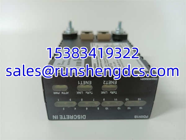
The GE IS220PDIIH1B (part number 336A5026ADP1) is an industrial automation control module belonging to GE’s Mark VIe Speedtronic control system platform. This I/O pack serves as a critical interface between the Mark VIe controller and field devices in gas turbine, steam turbine, and industrial process control applications, providing data processing, logic execution, and signal conditioning capabilities.
As part of the Mark VIe ecosystem, the IS220PDIIH1B is designed for high-reliability operation in harsh industrial environments. The module operates on a 24VDC power supply and features both serial communication interfaces (RS232/RS485) supporting Modbus RTU protocol, enabling integration with auxiliary devices, legacy equipment, and distributed control systems. The compact DIN rail mount design with terminal block connections simplifies installation and maintenance within Mark VIe I/O chassis or standalone control cabinets.
The IS220PDIIH1B is certified for use in hazardous locations, carrying UL listing for Class I, Division 2, Groups A, B, C, D (T4 temperature class) and ATEX certification (Ex nA II CT4 Gc), making it suitable for installation in areas where flammable gases or vapors may be present under abnormal conditions. The module’s operating temperature range of -40°C to +70°C and IP20 protection rating ensure reliable performance across diverse environmental conditions, from arctic installations to hot industrial facilities.
This module is typically used in conjunction with compatible Mark VIe terminal boards such as the IS200TBCIH2C, IS200STCIH1A, IS400TBCIH2C, and other配电 boards specified in GE documentation GEH-6725. The IS220PDIIH1B handles discrete signal processing, communicating with the Mark VIe controller over the IONet Ethernet backbone while simultaneously managing local serial communication with field instruments.
QA/QC Transparency SOP
- Intake & Origin Verification: Confirm the catalog number is IS220PDIIH1B and the part number matches 336A5026ADP1. Verify the module’s origin — whether it came from a Mark VIe system teardown, surplus stock, or new-old-stock inventory. Check the PCB date code, revision level (e.g., Rev. C as marked on some units), and compare against your system requirements. Inspect the physical condition: look for bent pins on connectors, corrosion on terminal blocks, damaged DIN rail clips, or signs of overheating on components.
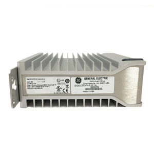
- Visual Inspection: Examine the PCB for swollen capacitors, burnt components, cold solder joints, or traces damaged by vibration. Check the terminal block connectors for secure mounting and intact screw threads. Verify that all surface-mount components are properly seated and there is no evidence of moisture ingress or conformal coating degradation. Inspect the module label for legibility — the label should clearly show the model number, part number, power specifications (28V DC, 0.15A DC), and certification marks (UL, CE, ATEX).
- Power-Up Test: Connect the module to a regulated 24VDC power supply through the terminal block. Observe the front panel LEDs during power-on. The PWR (power) LED should illuminate steadily, indicating proper power reception. If the module has an ATTN (attention) or fault LED, verify it is not illuminated under normal power-up conditions. Measure the current draw — it should be approximately 0.15A DC as specified on the label.
- Communication Interface Test: Connect a serial cable to the RS232/RS485 port and verify communication using a terminal emulator (e.g., PuTTY, HyperTerminal). Configure the serial port parameters (baud rate, parity, stop bits) to match the module’s default settings or your system configuration. Send a Modbus RTU query and verify the module responds correctly. Test both RS232 and RS485 modes if the module supports configurable serial interface selection.
- I/O Signal Test: If the module has discrete input or output channels, apply test signals to the input terminals and verify the module correctly registers the input state. For output channels, command the module to toggle outputs and verify the output terminals switch correctly using a multimeter or test lamp. Verify channel-to-channel isolation by checking that activating one channel does not affect adjacent channels.
- Environmental Stress Test (if applicable): For critical applications, perform a burn-in test by operating the module at elevated temperature (up to +60°C) for 24–48 hours while monitoring for intermittent faults. Verify that the module maintains communication and I/O functionality throughout the test. Check that the module does not exceed its specified temperature rise under full load conditions.
- Final QC & Packaging: After passing all tests, inspect the terminal block screws for proper torque and install terminal covers if provided. Verify the DIN rail clip is secure and the module mounts properly on a standard 35mm DIN rail. Document all test results including power-up status, communication test results, I/O verification, and current draw measurements. Package in an ESD-safe bag with desiccant and shock-absorbing foam. Include a test report with all verification data.
Field Engineer Gotchas
- vs IS220PDIAH1B: These are different modules in the Mark VIe family. The PDIAH1B is a 24-channel discrete input module, while the PDIIH1B is a general-purpose I/O/control module with serial communication capabilities. Do not substitute one for the other — they have different firmware, pinouts, and functions. Always verify the exact model number on the module label before installation.
- Power supply voltage: The module is rated for 24VDC nominal, with a label specification of 28V DC at 0.15A. Do not connect this module to a 125VDC or 48VDC supply — it will be destroyed. Verify your Mark VIe rack power supply or external 24VDC supply is properly regulated before powering the module.
- Serial communication configuration: The RS232/RS485 interface may require specific configuration (baud rate, parity, Modbus address) to communicate with your system. If the module is not responding to serial queries, verify the communication parameters match between the module and the master device. Some Mark VIe modules ship with default settings that may need to be changed via ToolboxST or a configuration utility.
- Hazardous location installation: If installing in a Class I, Div. 2 or ATEX Zone 2 area, ensure the module is properly mounted in a certified enclosure and all wiring meets the requirements for hazardous location installations. The module’s T4 temperature rating means the surface temperature will not exceed 135°C under fault conditions — verify this is compatible with the gas group present in your installation area.
- Terminal block torque: The terminal block screws should be torqued to the manufacturer’s specification (typically 0.5–0.6 N·m for small terminal blocks). Over-tightening can strip the threads or damage the terminal block housing, while under-tightening can cause intermittent connections that lead to communication failures or I/O errors.
- DIN rail mounting: Ensure the module is properly seated on the DIN rail and the retaining clip is fully engaged. A loosely mounted module can vibrate loose in high-vibration environments (near turbines, compressors, or large motors), causing intermittent power or communication loss.
- Firmware compatibility: If the is being used in a Mark VIe system with a specific controller firmware version, verify that the module’s firmware is compatible. Mismatched firmware versions between the controller and I/O modules can cause communication errors or unexpected behavior. Use ToolboxST to check firmware versions and upgrade if necessary.
- ESD sensitivity: Like all Mark VIe modules, the is sensitive to electrostatic discharge. Always use proper ESD precautions (wrist strap, ESD mat) when handling the module. Never touch the PCB traces or connector pins directly.
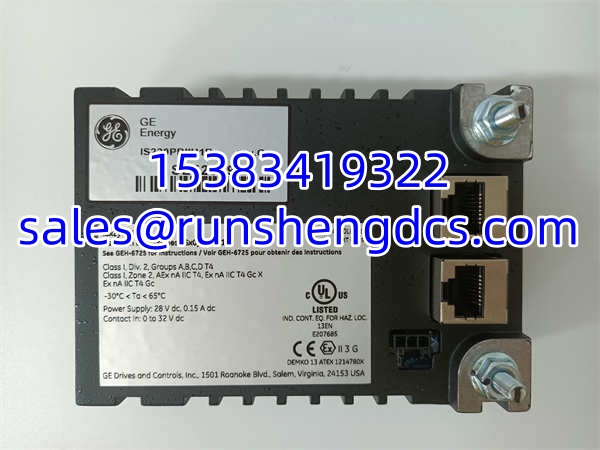
GE IS220PDIIH1B
Application Scenarios
- Gas turbine auxiliary control: In a 7FA gas turbine installation, the module is used to interface with auxiliary systems such as the lube oil system, cooling water system, and fuel gas conditioning system. The module’s serial communication port connects to a Modbus RTU-enabled flow transmitter on the fuel gas line, reading real-time flow data and transmitting it to the Mark VIe controller over IONet. The discrete input channels monitor pressure switches on the lube oil system, providing safety interlock signals to the turbine protection logic. The module’s hazardous location certification allows it to be mounted in the turbine enclosure area, reducing wiring distance and improving signal integrity.
- Steam turbine retrofit project: During a retrofit of a legacy Frame 6 steam turbine, the module replaces an older Mark V I/O pack that had failed. The module’s RS485 port connects to a remote I/O rack via Modbus RTU, collecting valve position feedback from the turbine’s governing system. The discrete outputs control indicator lights on a local operator panel, providing visual status of turbine operating modes (startup, running, tripped). The DIN rail mount design allows quick installation in the existing control cabinet without modifying the panel layout.
- Compressor station control: At a natural gas compressor station, multiple modules are installed in a Mark VIe I/O chassis to monitor and control compressor auxiliary systems. One module handles communication with a Modbus-enabled vibration monitoring system, reading bearing vibration data and transmitting it to the controller for trend analysis and alarm generation. Another module monitors discrete signals from flame detectors and gas detectors in the compressor enclosure, providing critical safety inputs to the turbine protection system. The module’s wide operating temperature range (-40°C to +70°C) ensures reliable operation in the unheated compressor building during winter.
FAQ
Q: What’s the difference between and IS220PDIAH1B?
A: These are different modules in the Mark VIe family. The IS220PDIAH1B is a 24-channel discrete input module designed specifically for acquiring 24VDC switching signals from field devices like limit switches and contactor contacts. The is a general-purpose I/O/control module with serial communication capabilities (/, Modbus RTU). They have different firmware, pinouts, and functions — do not substitute one for the other.
Q: What software do I use to configure the ?
A: The is configured using GE’s ToolboxST engineering software, which runs on a Windows PC. ToolboxST connects to the Mark VIe controller via Ethernet and allows you to configure I/O module parameters, monitor real-time data, view diagnostics, and update firmware. For serial communication configuration (Modbus RTU parameters), you may need to use the module’s configuration utility within ToolboxST or a serial configuration tool.
Q: Can this module be used in hazardous locations?
A: Yes. The is certified for Class I, Division 2, Groups A, B, C, D (T4 temperature class) per UL standards, and carries ATEX certification (Ex nA II CT4 Gc) for Zone 2 hazardous areas. This makes it suitable for installation in areas where flammable gases or vapors may be present under abnormal conditions, such as near gas turbines, compressors, or fuel handling equipment.
Q: What terminal boards is this module compatible with?
A: The is compatible with various Mark VIe terminal boards including IS200TBCIH2C, IS200STCIH1A, IS200STCIH8A, IS400TBCIH2C, IS400STCIH1A, and others specified in GE documentation GEH-6725. Always consult the Mark VIe hardware manual for the complete list of compatible terminal boards for your specific application.
Q: Is this module still available new?
A: The is part of GE’s Mark VIe platform, which is still supported by GE Vernova. However, specific revisions may be superseded by newer versions. New and surplus units are available from GE and independent suppliers. For critical applications, I’d recommend keeping a verified spare in your inventory — while the module is robust, the electronic components can fail after years of continuous operation in harsh industrial environments.
Q: Can I hot-swap this module?
A: Mark VIe I/O modules generally support hot-swap in redundant system configurations. However, the ‘s hot-swap capability depends on your specific system configuration and the function it performs. If the module is handling critical safety signals, removing it may cause a turbine trip even in a redundant system. Always consult the Mark VIe maintenance manual and your plant’s procedures before performing hot-swap operations.