
Description
Key Technical Specifications
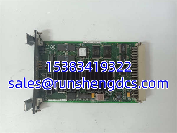
- Processor Speed: 60 MHz Digital Signal Processor
- Logic Architecture: Custom ASIC + Standard Memory Components
- Series Compatibility: GE Mark VI & EX2100
- Firmware Types: Application Code, Config Parameters, Bootloader
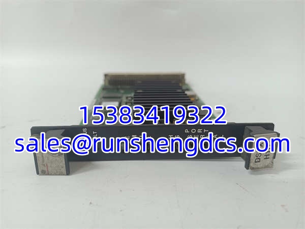
- Status Indicators: Red (Fault) & Green (Status) LEDs
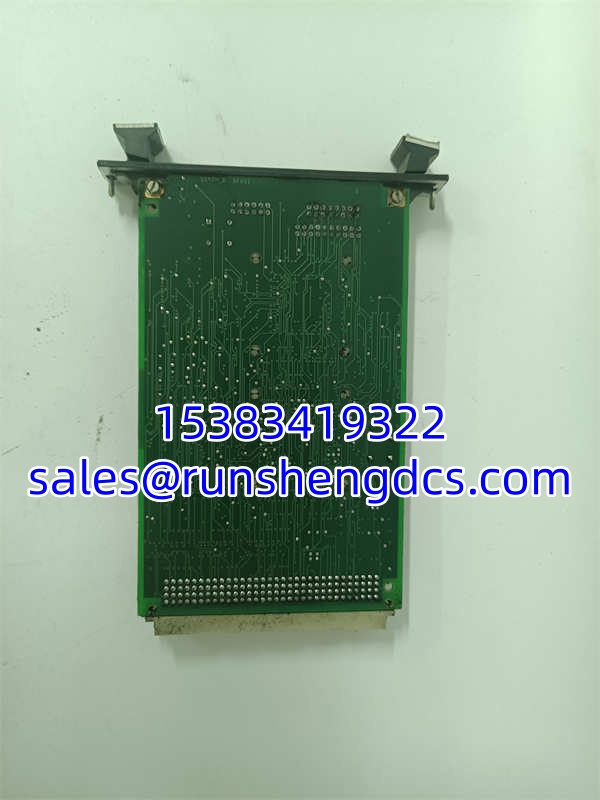
- I/O Connectors: Backplane (P1), Vertical Pin (P7), Eng. Monitor (P6), DSP Sim (P5)
- PCB Dimensions: ~8.5″ L x ~5.0″ W (Board only)
- Total Width (with Faceplate): ~7.0″
- Total Thickness: ~1.0″
- Faceplate Marking: 259B2431FBG08
- ESD Sensitivity: High (Static Sensitive Device)
Product Introduction
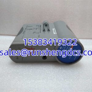
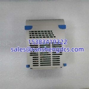
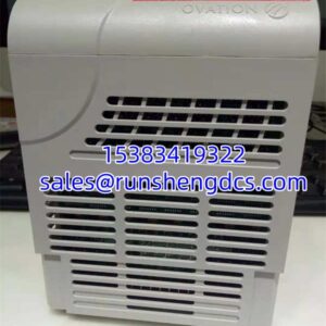
Turbine excitation control demands microsecond-level precision, and the GE IS200DSPXH1DBC is the board that actually crunches the numbers to keep your generator stable. Sitting in the Mark VI or EX2100 rack, this DSP card handles the heavy lifting of control algorithms while a dedicated ASIC manages custom logic and front-panel diagnostics. I’ve seen plants try to limp along with a degraded DSP, but when you need that 60MHz processing power for a grid fault, there is no substitute.
This specific GE IS200DSPXH1DBC revision is a workhorse, but it is notoriously picky about its catalog number. The trailing letters matter immensely; a “DBD” will not talk to a “DBC” without serious reconfiguration headaches. It features dual LEDs on the faceplate—green for status, red for fault—which are your first line of defense when troubleshooting a silent rack failure. My advice: treat this board like a precision instrument, not a relay. The ASIC and DSP generate heat, and the conformal coating can crack if you flex the board during installation.
Quality SOP & Tech Pitfalls
Before any GE IS200DSPXH1DBC leaves our facility, we run a full bench validation. We start with a visual inspection under magnification to check for micro-cracks in the conformal coating or cold solder joints on the BGA components. Next, it goes on a live Mark VI test rack to verify the 60MHz clock, ASIC logic, and LED functionality. We use a Fluke 115 to check power rail regulation and insulation resistance, verify the P1 backplane connector pin integrity, and log the exact firmware version before sealing it in anti-static packaging.
The most common field disaster I see is technicians ignoring the catalog suffix. I once watched a crew install a “DBC” into a slot configured for “DBD,” and the board sat there with a solid red fault LED for three hours while they chased phantom wiring issues. The firmware application code is tied to that specific suffix. Also, never underestimate ESD. I’ve seen this board fail instantly because a tech didn’t ground himself before touching the P6 engineering monitor port. Always wear a wrist strap and handle by the edges.
Installation & Configuration Guide
- Pre-Installation: ⚠️ VERIFY EXACT CATALOG NUMBER. Check the edge of the old board for the full alphanumeric code. Photograph the DIP switches, jumper settings, and LED status before removal. Ensure you are grounded and working on an ESD-safe mat.
- Removal: Disconnect the P6 and P5 front-panel cables first. Release the backplane locking mechanism and slide the GE IS200DSPXH1DBC out smoothly. Do not pry; the P1 backplane connector is fragile.
- Installation: MATCH ALL JUMPER AND DIP SWITCH SETTINGS. This prevents 90% of startup communication errors. Align the GE IS200DSPXH1DBC carefully with the P1 backplane connector and seat it firmly. Reconnect the front-panel cables and verify the faceplate is flush.
- Power-On & Testing: Restore control power and watch the front-panel LEDs. You should see the green Status LED blink during boot, then settle to a steady state. Use the Toolbox application to verify the application code loaded correctly and check for any active fault codes in the Mark VI diagnostics.
GE IS200DSPXH1DBC
Compatible Replacement Models
| Compatibility | Model | Notes |
|---|---|---|
| ✅ Drop-in Replacement | GE IS200DSPXH1DBC | Exact hardware/firmware match. Verify suffix. |
| ⚠️ Software Compatible | GE IS200DSPXH1DBD | Same hardware, different firmware/application code. Requires parameter reload and logic verification. Budget ~2-4 hours engineering. |
| ❌ Hardware Mod Required | GE IS200DSPXH1CAA | Different DSP architecture and faceplate. Not a direct swap. Full system reconfiguration required. Do not use. |
Frequently Asked Questions (FAQ)
Can I swap a DBC for a DBD without changing anything?
No. The suffix indicates the specific application code and ASIC logic loaded at the factory. A DBD might have different exciter control parameters or drive logic. If you force it, you will likely get a configuration mismatch fault or, worse, incorrect control behavior during a grid event. Always match the suffix or plan for a full parameter reload.
The red Fault LED is solid. Is the board dead?
Not necessarily. Check the Mark VI diagnostics via the engineering monitor port (P6). A solid red LED often indicates a watchdog timeout or communication loss with the R core, not a hard silicon failure. It could be a backplane issue, a power supply dip, or a corrupted application code. Pull the diagnostic log before condemning the board.
How do I load new configuration parameters?
Use the Toolbox application for general parameters. For exciter-specific parameters, use the Unit Data Highway application. Drive parameters typically go over Ethernet, serial, or ISBus. Never attempt to flash the bootloader unless instructed by GE support; a bad bootloader flash will brick the permanently.
Is this board sensitive to temperature?
Yes. The 60MHz DSP and ASIC generate significant heat. Ensure the Mark VI cabinet fans are operational and the air filters are clean. I’ve seen these boards fail prematurely in cabinets running at 55°C+ because the thermal paste on the DSP had dried out. Keep the ambient temp below 50°C for long-term reliability.
Can I test this board on a bench without the full Mark VI rack?
Only with a dedicated DSP simulator connected to the P5 port. The board will not boot or report meaningful status without the proper backplane termination and R-core communication. Bench testing requires the full Mark VI test environment or a validated simulator setup.