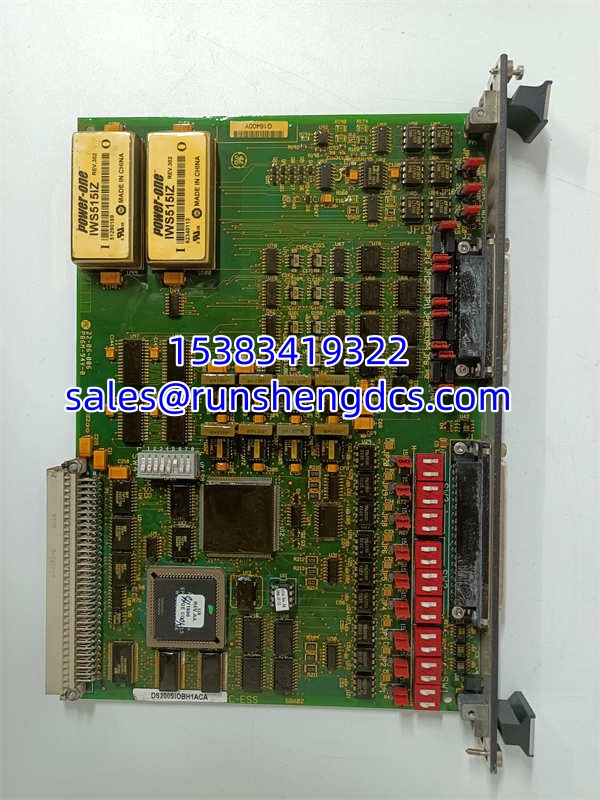

Description
Key Technical Specifications
| Parameter | Specification |
|---|---|
| Product Type | Analog I/O Board (TCQA) |
| Platform | GE Speedtronic Mark V |
| Bus Architecture | VME (occupies one full VME slot) |
| Signal Types | LVDT, Servo Valve, Thermocouple, 4-20mA I/O, Vibration, Pulse, Voltage, Generator/Line Signals |
| Analog Output Current | 0-20mA |
| Max Lead Resistance | 15Ω |
| Operating Temperature | -30°C to +65°C |
| Power Supply | 24VDC output support |
| Coating | Conformal coating (moisture/chemical protection) |
| Connectors | 3PL (data bus), JE (pulse/generator/line signals), JF (LVDT), JG (vibration), JB (4-20mA) |
| Hardware Jumpers | J1/J2 (mA output circuit selection), J5/J6 (20mA or 200mA range), J7 (RS232 card test), J8 (oscillator) |
| Diagnostic | LED status indicator |
Product Introduction
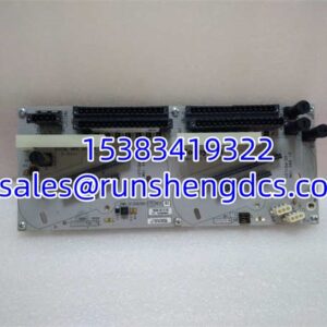
The GE DS200SIOBH1ACA is the TCQA (Terminal board Conditioned Analog) board within GE’s Speedtronic Mark V turbine control system. It serves as the central analog signal conditioning hub, receiving raw signals from terminal boards mounted on I/O cores R1, R2, and R3, then scaling and conditioning them for use by the turbine control processor.
This board handles an exceptionally wide range of signal types: LVDT position feedback, servo valve drive outputs, thermocouple temperature inputs, 4-20mA process signals (such as compressor stall detection and fuel flow pressure), vibration inputs, relay driver outputs, pulse inputs, and generator/line signals. The conditioned signals are then routed via the 3PL connector to the STCA board for COREBUS transmission, while generator and line signals pass through the JE connector to/from the TCQC board.
The board features conformal coating for protection against moisture, dust, and chemical exposure, making it suitable for the harsh environments typical of gas turbine installations. Bottom line: this is the signal backbone of your Mark V turbine control system — without it, the controller cannot see or act on any analog process variable.
QA/QC Transparency SOP
- Intake & Origin Verification: Confirm part number DS200SIOBH1ACA matches the physical label and revision. Inspect the VME edge connector for bent pins, corrosion, or arcing marks. Check conformal coating for cracks, peeling, or moisture damage.
- Live Functional Testing: Installed in a Mark V VME test rack. Injected known 4-20mA signals at JB connector and verified scaled output via diagnostic interface. Verified LVDT input scaling at JF connector. Confirmed thermocouple cold junction compensation accuracy at JA connector.
- Electrical Parameter Tests: Measured 24VDC output under load. Verified analog output current range (0-20mA) at specified lead resistance. Checked isolation between signal channels and VME backplane. Confirmed LED diagnostic indicator function.
- Jumper/Config Verification: Documented all jumper positions (J1, J2, J5, J6, J7, J8) and compared against customer’s existing board configuration. Verified switch block settings match original. This is critical — mismatched jumpers cause signal scaling errors.
- Final QC & Anti-Static Packaging: VME connector pins cleaned and inspected for straightness. Sealed in anti-static bag with desiccant. Hard-shell case to prevent connector damage during transit.
Field Engineer Gotchas
- Jumper Configuration is Critical: The DS200SIOBH1ACA has multiple hardware jumpers (J1, J2, J5, J6, J7, J8) that define mA output circuit selection and current range (20mA vs 200mA). When replacing a board, you must copy the exact jumper positions from the old board to the new one. Mismatched jumpers will cause incorrect signal scaling, potentially leading to turbine trip or uncontrolled operation.
- VME Connector Fragility: The VME P1 edge connector is precision-machined and expensive to replace. Never force the board into the slot. Align perfectly, apply even pressure with both hands, and slide in smoothly. Bent pins can damage the VME backplane, turning a simple board swap into a major outage.
- Conformal Coating Inspection: If the coating is cracked or peeling, moisture ingress can cause intermittent signal drift or corrosion. This is especially common in coastal or high-humidity turbine installations. Don’t ignore cosmetic coating damage — it’s a leading indicator of future failures.
- Signal Routing Complexity: The TCQA board routes signals through multiple connectors (3PL, JE, JF, JG, JB, JA). If you’re troubleshooting a signal path issue, you need to trace from the terminal board → TCQA → STCA/TCQC. A fault at any point in this chain can appear as a TCQA failure. Don’t replace the board until you’ve verified the terminal board and downstream connections.
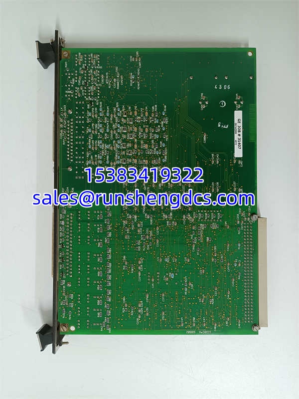
GE DS200SIOBH1ACA
Application Scenarios
- Gas Turbine Power Generation: Combined cycle and simple cycle gas turbine plants using GE Speedtronic Mark V controls. The DS200SIOBH1ACA conditions critical signals including turbine exhaust temperature (thermocouples), fuel flow, compressor discharge pressure, and vibration monitoring.
- Steam Turbine Control: GE steam turbine installations where the Mark V system manages governor control, extraction pressure, and condenser vacuum. LVDT feedback from servo valves passes through this board.
- Industrial Cogeneration: Manufacturing facilities with GE turbine-driven generators providing both electricity and process steam. The board’s 4-20mA channels handle process instrumentation like steam flow and header pressure.
FAQ
What does “TCQA” stand for?
TCQA = Terminal board Conditioned Analog board. It’s the GE internal designation for this specific I/O board type within the Mark V architecture.
Is DS200SIOBH1ACA compatible with Mark VI or Mark VIe?
No. The is specific to the Mark V platform. Mark VI/VIe systems use different I/O architectures (e.g., IS200/IS215 series). They are not cross-compatible.
Both are TCQA boards for Mark V, but the suffix indicates different hardware revisions. The “-ACA” revision may have updated components or firmware compared to “-ABA”. Always match the exact revision when replacing, or verify jumper compatibility.
Can I hot-swap this board?
No. The Mark V VME backplane is not designed for hot-swapping I/O boards. You must de-energize the control system before removing or inserting the . Hot-swapping risks VME backplane damage and control system corruption.
How do I verify the board is functioning correctly?
Use the Mark V diagnostic interface to monitor analog input values while injecting known signals at the terminal board. Compare the displayed engineering units against your injected values. Also check the LED status indicator — a steady light indicates normal operation.
What causes this board to fail?
Common failure modes include: conformal coating degradation leading to moisture damage, VME connector pin corrosion, electrolytic capacitor aging, and jumper misconfiguration after replacement. Boards in high-vibration or high-humidity environments fail faster.
Is this board still supported by GE?
The Mark V series is considered legacy by GE. Official support has been largely transitioned to Mark VIe and newer platforms. However, third-party suppliers continue to stock and refurbish boards. For long-term reliability, consider planning a control system migration.