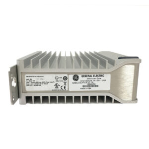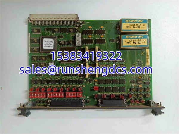

Description
Key Technical Specifications
| Parameter | Value |
|---|---|
| Product Model | DS200SIOBH1ABA |
| Manufacturer | GE (General Electric) |
| Product Type | SC2000 VME I/O Board (SIOB) |
| Platform | Speedtronic Mark V Turbine Control System |
| Mounting | VME Rack, P1 Connector (full VME slot) |
| Hardware Jumpers | 20 (some factory-fixed, non-movable) |
| DIP Switches | 18 total (3 blocks × 6 switches) |
| Diagnostic Indicator | Front-panel LED (illuminated = normal operation) |
| Interface Connector | 40-pin |
| Application | Gas, Steam, and Wind Turbine Control |
| Product Status | Legacy / Discontinued |
Product Introduction
If your Mark V rack just threw a board fault at 2 AM and the only spare you can source is a surplus DS200SIOBH1ABA, the first thing you need to know is this: it is not a plug-and-play swap. The DS200SIOBH1ABA is a SC2000 VME Serial I/O Board (SIOB) sitting inside the Mark V Speedtronic turbine control architecture. It occupies a full VME slot via the P1 backplane connector and serves as the hardware-level interface between field instruments — LVDTs, servo valves, thermocouples, 4-20mA loops, vibration sensors — and the core Mark V processor. Every signal that reaches the turbine protection logic passes through boards like this one first.
The DS200SIOBH1ABA ships from the factory with all 20 jumpers set to default positions and all 18 DIP switches in their default states. Neither of those defaults will match your turbine. This board demands physical hardware configuration — jumper-by-jumper, switch-by-switch — to replicate the exact settings of the board it replaces. A single misplaced jumper can scale a 4-20mA signal incorrectly or disable an oscillator startup circuit. The front-panel LED gives you one piece of immediate feedback: if it is lit, the board is receiving backplane power and reporting normal status. That is the extent of its onboard diagnostics. For a legacy platform with no OEM production support, having a correctly configured, bench-tested DS200SIOBH1ABA on the shelf is not optional — it is the difference between a 4-hour outage and a 4-week outage.
QA/QC Transparency SOP
- Intake & Origin Verification: Verify the rear label reads exactly “DS200SIOBH1ABA” — not DS200SIOBH1AAA or DS200SIOBH1ACA. Inspect the VME P1 connector pins for bent or corroded contacts. Check the 40-pin interface connector for oxidation. Photograph all 20 jumper positions and all 18 DIP switch positions before touching anything. Confirm no visible burn marks, cracked solder joints, or moisture damage on the PCB.
- Live Functional Testing: Seat the board in a verified Mark V VME test rack. Apply backplane power. Confirm the front-panel LED illuminates within 5 seconds of power-up. Verify communication handshake with the Mark V processor via COREBUS. If test equipment is available, inject known reference signals through the 40-pin connector and verify scaled outputs at the processor interface.
- Electrical Parameter Tests: Using a Fluke 87V or equivalent, measure backplane voltage at the P1 connector (verify +5VDC and ±12VDC rails within tolerance). Perform continuity check across all 40 pins to the corresponding test points on the PCB. Megger test isolation between signal ground and chassis ground (minimum 10 MΩ at 250VDC).
- Firmware/Config Verification: The is a hardware-configured board — there is no firmware to flash. However, verify that any associated Mark V project files reference the correct board type and slot assignment. Document the final jumper/switch configuration and archive it with the board’s serial number for traceability.
- Final QC & Anti-Static Packaging: Clean the PCB with isopropyl alcohol (no residue). Apply conformal coating inspection under UV light if applicable. Place in ESD-safe bag with desiccant pack. Attach QC tag documenting: serial number, jumper map, switch map, LED test result, and date of test.
Field Engineer Gotchas
Jumper Configuration Mismatch
The has 20 jumpers. Some are factory-fixed and cannot be moved. The rest control signal scaling, current ranges, RS232 test modes, and oscillator behavior. If you install a new board without copying the exact jumper map from the old board, the turbine will see garbage data — or no data at all.
Solution: Before removing the old board, photograph every jumper position. Label them JP1 through JP20. Replicate on the new board before insertion. Do not rely on the printed silkscreen alone — revision differences can shift jumper locations between boards.
War Story: A combined-cycle plant in Texas swapped a during a forced outage. Skipped the jumper transfer to save 20 minutes. Board seated fine, LED lit. Turbine wouldn’t sync — exhaust thermocouple readings were scaling to 2000°F on a cold start. Root cause: one jumper controlling the thermocouple range was in the wrong position. Cost: 6 hours of additional downtime and a very angry plant manager.
DIP Switch Block Errors
Three blocks of 6 switches (18 total) control board-level behavior. These are easy to misread under poor lighting, especially on a board that has been in service for 15+ years and has faded silkscreen.
Solution: Use a flashlight and a magnifying glass. Verify each switch position against the old board, not against memory. Switch blocks are typically labeled SW1, SW2, SW3. Document the ON/OFF state of all 18 switches before and after.
Blunt Warning: If you guess on even one switch, you could disable a protection circuit. There is no software override.
VME Backplane Connector Damage
The P1 connector is a high-density edge connector. Repeated insertions, vibration, or improper removal can bend pins. A bent pin on the +5VDC or ground rail will cause intermittent faults that look like processor errors.
Solution: Always remove the board using both hands, pulling straight out perpendicular to the backplane. Never rock or twist. Inspect P1 pins with a magnifier before every installation. If more than 2 pins are bent, send the board for rework — do not force it.
ESD Damage During Handling
Mark V boards are legacy. Replacement cost for a damaged can exceed 3,000–5,000 on the surplus market. A single ESD event can destroy the onboard ICs without visible damage.
Solution: Wear a grounded wrist strap at all times. Place the board on a flat ESD-safe mat. Never set it on a concrete floor, metal rack rail, or your knee.
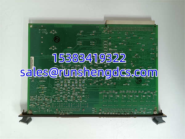
GE DS200SIOBH1ABA
Application Scenarios
Gas Turbine Exhaust Temperature Monitoring: Combined-cycle plants rely on the to condition thermocouple signals from the turbine exhaust section. These signals feed directly into the Mark V temperature control algorithm, which governs fuel split and IGV positioning. Incorrect scaling on this board means the controller sees false exhaust temperatures — either tripping the unit unnecessarily or, worse, allowing an overtemperature condition to persist.
Steam Turbine Valve Position Control: The board interfaces with LVDT sensors on main steam control valves. LVDT outputs are low-level AC signals that require precise scaling before the Mark V processor can use them for position feedback. The handles this conditioning in hardware, providing deterministic response with no software latency.
Wind Turbine Pitch and Generator Monitoring: In GE wind turbine installations running the Mark V platform, the processes pitch actuator feedback and generator line signals. The electrically noisy nacelle environment demands hardware-level signal conditioning that software filtering alone cannot provide.
FAQ
No. The Mark V VME backplane is not designed for hot-swap operations. Removing or inserting a board while the rack is energized can cause voltage transients on the backplane that may trip the processor or damage adjacent cards. Always de-energize the specific VME slot or the entire rack before swapping.
Mechanically, yes — they share the same form factor and VME connector. Electrically, maybe not. Revision differences (the last letter suffix) can indicate changes in component values, jumper layouts, or supported signal types. Always cross-reference the jumper map and switch configuration between the old and new board. If the silkscreen labels don’t match, consult the GE installation manual for that specific revision before proceeding.
My Mark V system is being migrated to Mark VIe. Do I still need this board?
No. The Mark VIe platform uses a completely different I/O architecture (IONet-based, with IS200/IS210 series cards). The is incompatible with Mark VIe hardware. However, if your migration is phased and the Mark V rack remains operational during the transition, keep at least one tested spare on hand.
The front-panel LED is not lighting up after installation. Is the board dead?
Not necessarily. First, verify that the VME rack backplane is supplying power to that slot. Check the rack power supply status LEDs. Reseat the board firmly on the P1 connector. If the LED still does not illuminate after confirming power at the backplane, the board likely has a failed voltage regulator or blown fuse on the PCB — at that point, it needs bench-level repair or replacement.
How do I know if the jumper positions on my replacement board are correct?
You don’t — unless you documented the original board’s configuration before removal. There is no “correct” universal setting. The correct configuration is whatever matches your specific turbine application. If you did not document the old board, you will need to obtain the jumper configuration from your plant’s maintenance records, the original GE installation manual, or the Mark V project documentation.
Since GE discontinued the Mark V platform, there is no OEM lead time. Availability depends entirely on the surplus and refurbished market. Typical lead times range from 1–4 weeks for in-stock surplus units to 8–12 weeks if the board needs to be sourced internationally or refurbished. Bottom line — if you are running Mark V, you should have at least one spare of every critical board type in your storeroom right now.