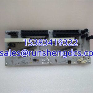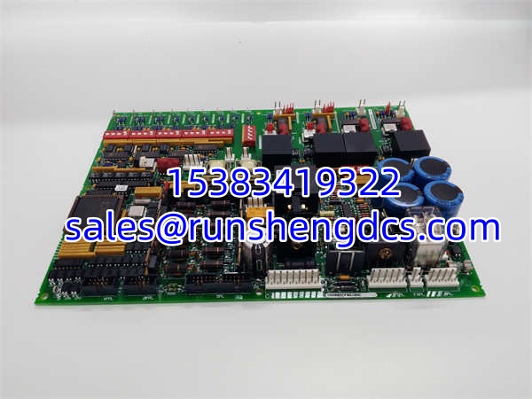

Description
Key Technical Specifications
- Model Number: DS200DCFBG1BNC
- Manufacturer: GE Fanuc
- Series: IC697 PLC / Speedtronic
- Expansion Capacity: Supports up to 7 additional IC697 racks
- Max Cable Length: 50 feet (15 meters) total interconnecting cable
- Slot Requirement: Occupies 1 slot, must be installed in Slot 1
- Connectors: Dual connectors for upstream and daisy-chain routing
- Status Indicators: Three green LEDs (Module, Activity, Terminator)
- Hold Last State: Supports output hold during CPU communication loss
- Configuration: No DIP switches, software-configured into PLC system
Functional Role & Application Analysis
The GE DS200DCFBG1BNC serves as the critical bus receiver module for expanding IC697 PLC systems. It provides a high-speed parallel bus expansion interface that allows a main CPU rack to communicate with up to seven additional expansion racks. This module solves the physical I/O density limitation of a single chassis by enabling distributed, daisy-chained rack architectures. It occupies a single slot and must strictly be installed in slot 1 of the expansion rack.
Typical use cases include:
- PLC Rack Expansion: Extending the I/O capacity of large-scale IC697 PLC systems in power plants and heavy manufacturing facilities.
- Fault Isolation: Allowing maintenance teams to isolate and repair a faulty module within a specific expansion rack without disrupting the main CPU.
- Legacy System Maintenance: Replacing failed bus receiver modules in existing GE Fanuc infrastructure to maintain system integrity and prevent communication drops.
Our Quality Standard & Testing Process
We understand that the cost of an unreliable part is far greater than its purchase price. We have established a rigorous, multi-stage testing process to ensure every DS200DCFBG1BNC module we ship is 100% functional. Our testing validates both the physical bus connections and the logical communication protocols.
- Visual & Component Inspection: All units undergo professional cleaning and visual inspection. We verify the integrity of the dual backplane connectors and check the three green status LEDs for proper illumination.
- Live System Test: The module is installed in a live GE Fanuc test rack and run continuously to verify stable parallel bus communication and correct daisy-chain routing.
- Full-Function Diagnostics: We simulate CPU communication loss to test the Hold Last State functionality, ensuring output modules maintain their state during bus faults.
- Warranty Backing: Only parts that pass all diagnostic tests are approved for shipment and backed by our full 12-month warranty.
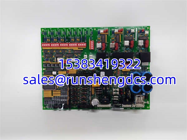
GE DS200DCFBG1BNC
Compatibility & Migration Paths
To ensure this DS200DCFBG1BNC is 100% compatible with your system, you must check these key compatibility points. Failure to verify this is a common project risk that can result in bus communication failures.
- Slot 1 Mandate: The Bus Receiver Module must always be installed in slot 1 of the expansion rack. Installing it in any other slot will prevent the rack from initializing.
- Terminator Requirement: You must install an I/O Bus Terminator Plug (such as DS200DCFBG1B) in the very last expansion rack in the daisy chain. Missing this terminator will cause bus reflection and system faults.
- Cable Length Limits: Do not exceed 50 feet (15 meters) of total interconnecting cable across all expansion racks. Exceeding this limit degrades the high-speed parallel bus signal.
- Get Expert Help: Unsure about your rack topology or terminator requirements? Contact our technical team today for a free compatibility check.