Description
Key Technical Specifications
- Model Number: DS200DCFBG1BLC
- Manufacturer: GE Boards & Turbine Control
- Series: Mark V / Mark VI / EX2000 Drive Systems
- AC Input Voltage: 38 to 115 VAC, 47-63 Hz
- DC Outputs: +5V (4A), ±15V (0.8A), ±24V (3A/1A)
- Feedback Processing: Onboard VCO (250 kHz nominal) for analog-to-digital conversion
- Protection: 3x Fuses (Fan, ±15V rails), Overcurrent & Short Circuit Protection
- Status Indicators: 2x LEDs, 1x Neon Lamp, 5x Test Points
- Configuration: 12x Jumpers, 7x DIP Switches
- Operating Temperature: -30°C to +70°C

GE-DS200DCFBG1BLC
Functional Role & Application Analysis
The GE DS200DCFBG1BLC serves as the critical power and signal conditioning front-end within GE Mark V turbine control racks and EX2000/DC2000 drive systems. It acts as the central hub that converts raw cabinet AC power into clean, isolated DC rails (+5V, ±15V, ±24V) required by sensitive logic and processor boards. Furthermore, it directly powers cabinet cooling fans, ensuring thermal management remains independent of the main logic bus.
Beyond power distribution, this board is responsible for vital analog feedback processing. It takes millivolt-level current and voltage signals from armature and field shunts, converting them into digital frequency outputs via an onboard Voltage-Controlled Oscillator (VCO). This isolates high-voltage transients from delicate microprocessors while providing precise 0.5% measurement accuracy without requiring external A/D converters.
Typical use cases include:
- Power Generation: Maintaining stable control power and excitation feedback in GE Mark V gas and steam turbine control cabinets.
- Industrial Drives: Supplying logic power and motor feedback signals in DC2000 and EX2000 drive racks.
- Preventative Maintenance: Replacing aging boards showing VCO frequency drift or failing ±15V regulators that cause intermittent drive faults.
- Legacy System Upgrades: Retaining the original power infrastructure when upgrading from DC2000 to EX2100 control algorithms.
Our Quality Standard & Testing Process
We understand that the cost of an unreliable part is far greater than its purchase price. A failing power board can cause turbine trips or drive faults that halt production. We have established a rigorous, multi-stage testing process to ensure every DS200DCFBG1BLC we ship is 100% functional and calibrated.
Our professional QC process includes:
- Visual & Component Inspection: Thorough inspection of all 12 jumpers, 7 DIP switches, and 3 fuse holders to ensure proper configuration and no physical damage or corrosion.
- Live System Test: Installed in a live Mark V/EX2000 test rack for 24 hours to verify stable DC rail output under load and proper fan operation.
- Full-Function Diagnostics: Oscilloscope verification of the VCO test points to confirm frequency accuracy within ±5%, alongside validation of all LED indicators and fuse monitoring circuits.
- Warranty Backing: Only parts that pass all diagnostic tests are approved for shipment and backed by our full 12-month warranty.
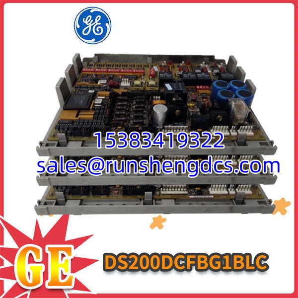
GE-DS200DCFBG1BLC
Compatibility & Migration Paths
To ensure this DS200DCFBG1BLC is 100% compatible with your system, you must check these key compatibility points. Failure to verify this is a common project risk that leads to processor resets or drive misfires.
Key verification steps:
- Input Voltage Verification: Confirm your Control Power Transformer (CPT) feeds exactly 38-115 VAC. Undervoltage will cause the +5V rail to fold back, resulting in unexpected processor resets.
- Jumper & DIP Switch Configuration: You MUST photograph and replicate the exact jumper and DIP switch settings from your failed board. Incorrect configuration will result in wrong output voltages or disabled feedback channels.
- Ribbon Cable Seating: Ensure the flat ribbon cables are seated evenly and tightened properly. A tilted connector will cause intermittent “missing phase” alarms under vibration.
- Get Expert Help: Unsure about your board’s configuration? Contact our technical team today for a free compatibility check. Provide a photo of your existing board’s jumpers for exact cross-reference validation.