
Description
Key Technical Specifications
| Parameter | Detail |
|---|---|
| Manufacturer | FOXBORO (Schneider Electric) |
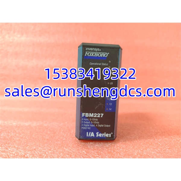
| Model | FBM227 |
| Order Code | P0927AC |
| Product Type | Mixed analog/digital I/O field bus module |
| Analog Inputs | 4 channels, 0-10 VDC, individually isolated |
| Analog Outputs | 2 channels, 0-10 VDC, individually isolated |
| Digital Inputs | 4 channels, 130 VDC max, paired isolation |
| Digital Outputs | 4 channels, 60 VDC external switching or 11 VDC internal 3-wire |
| Communication | Redundant 2 Mbps fieldbus (RS-485), Path A/B |
| Power Supply | 24 VDC +5%/-10%, redundant input |
| Power Consumption | 7 W max; heat dissipation 3 W max |
| Environmental Rating | G3 harsh environment (ISA S71.04) |
| Isolation | Analog: per-channel; Digital: paired isolation |
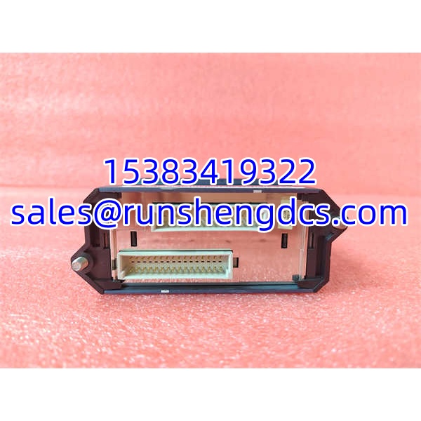
| Mounting | FBM baseplate or conversion mount, DIN-rail or rack |
| Status Indicators | Front-panel LEDs for module and channel status |
Product Introduction
Mixed-signal modules are the ones that cause the most confusion during a swap-out. The FBM227 is not a pure analog card and not a pure discrete card — it does both, and getting the terminal block wiring wrong means you either lose analog readings or kill digital outputs.
The P0927AC sits in an I/A Series FBM rack and talks to the control processor over a redundant 2 Mbps fieldbus. It handles four 0-10 V analog inputs (commonly used for valve position feedback or slide-wire potentiometers), two 0-10 V analog outputs (for driving positioners or remote indicators), four 130 VDC digital inputs, and four digital outputs with selectable external or internal switching. Bottom line — it is a legacy workhorse for retrofit and maintenance, not a new-design component. Confirm the analog/digital channel assignment against your control strategy before pulling the old card.
QA/QC Transparency SOP
- Intake & Origin Verification — Confirm model FBM227, order code P0927AC, PCB revision, and serial number. Inspect the extruded aluminum housing for damage, check connector pins for bent contacts, and verify the fieldbus cable connectors are intact.
- Live Functional Testing — Install into a compatible I/A Series FBM baseplate. Verify fieldbus registration on both Path A and Path B. Confirm front-panel LED status for module health and channel activity.
- Electrical Parameter Tests — Apply 24 VDC and measure current draw against the 7 W max specification. Using a Fluke multimeter, verify each of the four 0-10 V analog input channels reads accurately with a calibrated voltage source. Check digital input response at 24 VDC and 130 VDC thresholds.
- Firmware/Config Verification — Read module identification from the host processor. Confirm the module type code matches P0927AC and that the channel map aligns with the existing control strategy. Back up configuration before swap.
- Final QC & Anti-Static Packaging — Record analog channel accuracy, digital I/O response, fieldbus path redundancy test results, and LED behavior. Pack in anti-static material with nameplate photos, terminal block notes, and a test summary sheet.
Field Engineer Gotchas
- It is not a pure analog or pure digital card. The FBM227 mixes 4 AI, 2 AO, 4 DI, and 4 DO on one module. If your control strategy expects eight analog channels or eight discrete channels, this is the wrong card. Verify the I/O point list before ordering.
- Terminal block wiring must match channel type. The analog inputs are 0-10 V, not 4-20 mA. Wiring a 4-20 mA loop directly into an FBM227 AI channel will give incorrect readings unless an external shunt resistor is added. Confirm terminal assignments against the I/A Series wiring diagram.
- Digital output switching mode is wiring-dependent. The four DO channels can switch an external 60 VDC supply or use an internal 11 VDC source for 3-wire devices. Using the wrong wiring configuration means the output either does not energize the load or damages the connected device.
- Fieldbus path redundancy is not automatic. Both Path A and Path B cables must be connected and healthy for true redundancy. A single-path connection works but eliminates the fault-tolerance benefit.
- Firmware revision mismatch can cause recognition issues. A replacement FBM227 with a different firmware level may register on the bus but report incorrect channel data. Always compare the module ID and firmware readout against the host processor’s expected configuration.
FOXBORO FBM227 P0927AC
Application Scenarios
- Valve position feedback in process control. The four 0-10 V analog inputs accept slide-wire potentiometer signals from control valves, providing real-time position feedback to the DCS.
- Boiler management system I/O. Supports burner sequencing, flame detection interlocks, and mill/burner start-stop control with a mix of analog position feedback and discrete trip signals.
- Remote indicator and positioner drive. The two 0-10 V analog outputs drive local panel indicators or valve positioners where a dedicated analog output card would be overkill.
- Legacy I/A Series maintenance. Replaces a failed in an existing rack without re-engineering the I/O map, provided the terminal block wiring and firmware match.
FAQ
It is an I/O module, not a controller. It connects to an I/A Series control processor (such as an FCP or CP module) via the redundant 2 Mbps fieldbus and provides analog and digital signal conversion.
Can it accept 4-20 mA signals directly?
No. The analog inputs are specified as 0-10 VDC. To use 4-20 mA sensors, add external 250-ohm shunt resistors at the terminal block to convert current to voltage.
How many analog and digital channels does it have?
Four analog inputs (0-10 V), two analog outputs (0-10 V), four digital inputs (130 VDC max), and four digital outputs (60 VDC external or 11 VDC internal 3-wire).
Does it support redundant communication?
Yes. It accepts both Path A and Path B of the redundant 2 Mbps fieldbus. If one path fails, communication continues over the active path.
Yes. is the module type, and P0927AC is the order code/part number for that specific variant. Other suffixes (e.g., P0927BH) may indicate different revisions or firmware levels — verify before substitution.
What power supply does it need?
24 VDC with +5%/-10% tolerance, redundant input capable. Maximum power consumption is 7 W.
Can I hot-swap it?
The I/A Series FBM design supports removal and replacement without disconnecting field wiring, power, or communication cables. However, follow your site’s change management procedures and confirm with the host processor status before pulling a live module.