
Description
Product Introduction
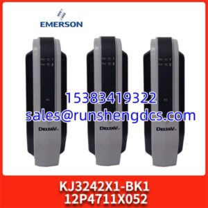
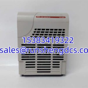
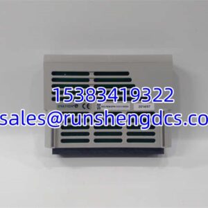
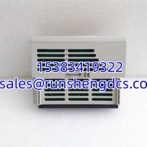
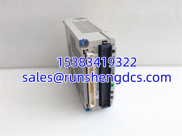
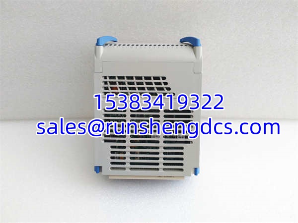
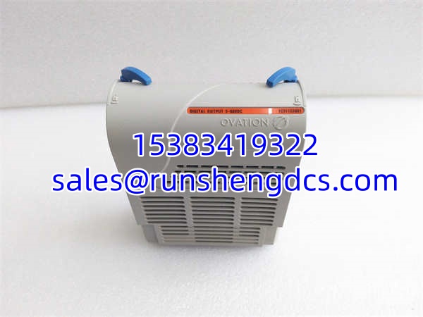
In the Ovation DCS architecture, the 1C31122G01 serves as the critical electronic module (E-Mod) for digital output control. It takes the logic commands from the controller and translates them into discrete switching actions to drive external field equipment like solenoid valves, motor starters, and indicator lights.
As an electronic module, it is designed to be paired with a corresponding characteristic module (P-Mod, such as the 1C31125G02) to provide the necessary relay contacts and power isolation. This modular approach ensures that the sensitive logic electronics are completely isolated from the harsh, high-current field environment, maximizing system reliability and safety.
Key Technical Specifications
- Module Type: Digital Output Electronic Module (E-Mod)
- Number of Points: 16 Channels
- Max Output Voltage: 60 VDC
- Typical Operating Voltage: 24 VDC
- Output Current: 0.5 A per channel (typical)
- Isolation: Field-to-Logic (Opto-coupler)
- Status Indication: LED per channel + Module OK (P, C, E indicators)
- Backplane Interface: Ovation Chassis
- Compliance: CE, UL Listed
Compatibility & Replacement Matrix
- 1C31122G01 → 1C31122G01: Direct Replacement — exact match.
- 1C31125G02 → N/A: Not a replacement. The 1C31125G02 is the Characteristic Module (P-Mod) that pairs with this E-Mod.
- 1C31219G01 → N/A: Not a replacement. The 1C31219G01 is a Relay Output Logic Module, which is a different architecture.
- 1C31122G02 → 1C31122G01: Direct Replacement — verify firmware revision before swapping.
Emerson 1C31122G01
Quality Inspection & SOP Transparency
Incoming Inspection
We verify the Emerson part number and serial number on the label. The unit must be free of physical damage, bent pins, or corrosion. We check the anti-static packaging to ensure it was stored correctly.
Live Functional Test
The module is installed in an Ovation rack and paired with a known-good 1C31125G02 P-Mod. Using a 24 VDC power supply and a multimeter, we force each of the 16 channels ON and OFF via the Ovation engineering tool. We verify that the corresponding channel LED illuminates and that the relay on the P-Mod clicks and passes voltage.
Electrical Parameter Test
We perform an insulation resistance test between the logic side and the field side to ensure the opto-isolators are intact. A continuity check is performed on the backplane connector pins to rule out any internal bus faults.
Firmware Verification
The module’s firmware revision is read via the Ovation cabinet software. We note if it requires a specific patch level to run on older cabinet versions.
Final QC & Packaging
After a 24-hour powered burn-in, the unit is sealed in an anti-static bag with a “Tested & Passed” label. The outer box uses double-wall cardboard to prevent crushing during shipping.
Common Replacement Pitfalls
E-Mod vs. P-Mod Confusion
This is the #1 mistake. The 1C31122G01 is only the electronic module. It has no relay contacts on it. It must be plugged into a base that holds a characteristic module (like the 1C31125G02). If you only order the 1C31122G01 and your old P-Mod is fried, your system won’t work. Always check both part numbers.
Firmware Revision Mismatch
Older Ovation cabinets sometimes reject newer module firmware. The module powers up but shows “Fault” on the console. Always check the cabinet’s software revision before ordering. If your cabinet is on R5.0, a module shipped with R6.0 firmware might need a downgrade.
Wiring Termination
The field wiring connects to the P-Mod terminal block, not the E-Mod. Do not attempt to wire directly to the electronic module. If you are replacing the entire assembly, take a photo of the wiring on the old terminal block before disconnecting.
ESD Precautions
The logic board is sensitive. Always clip a wrist strap to the grounded rack before handling. I’ve seen a module kill its internal opto-isolators because an engineer pulled it from the box while wearing a wool sweater. It worked for two days, then died mysteriously.
Diagnostic LED Misinterpretation
The ‘E’ LED on this module shows red if the card fuse is blown. If you see a red ‘E’ light, don’t just swap the module—check the field wiring for a short circuit first, or you’ll blow the fuse on the new module too.
Get these five right and you’ll cut rework time by most of the afternoon.
Emerson 1C31122G01
FAQ
Q: Is the 1C31122G01 a complete module?
A: It is the electronic portion. It must be paired with a characteristic module (P-Mod) like the 1C31125G02 to function as a complete digital output channel. The P-Mod provides the relays and terminal blocks.
Q: What’s the deal with the firmware? Will it work on my old R4.5 system?
A: The 1C31122G01 typically ships with firmware compatible with R5.0 and R6.0 systems. If your cabinet is on R4.5, the module will power up but show “Incompatible” on the console. You’ll need to order the module with the older firmware loaded, or upgrade the entire cabinet. Verify your system revision first.
Q: Can I hot-swap this module?
A: Yes. The Ovation system supports hot swapping for I/O modules. However, ensure the field wiring is de-energized before disconnecting the terminal block on the P-Mod. The logic side is safe to swap live, but the field side carries voltage—treat it like live electrical work.
Q: Is this brand new or refurbished?
A: We only list New Original (New Surplus) units. These are excess stock from decommissioned projects, never installed in a plant. They come in the original sealed box or with a verified anti-tamper seal.
Q: What if the ‘E’ LED is red?
A: A red ‘E’ LED indicates a blown fuse on the card. This is usually caused by a short circuit in the field wiring. Do not just replace the module without checking the field wiring first, or you will blow the fuse on the replacement.
Q: Do you have the matching P-Mod?
A: Yes, the standard P-Mod for this E-Mod is the 1C31125G02 (system-powered relay) or 1C31125G03 (locally-powered relay). Let us know your field voltage requirements and we can quote the complete assembly.