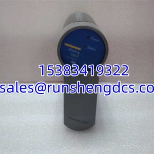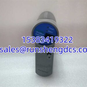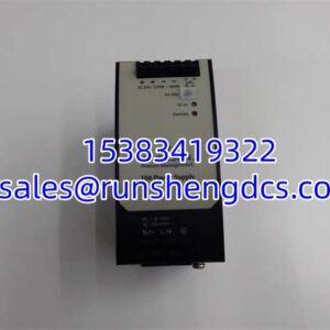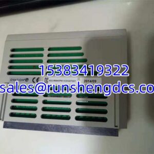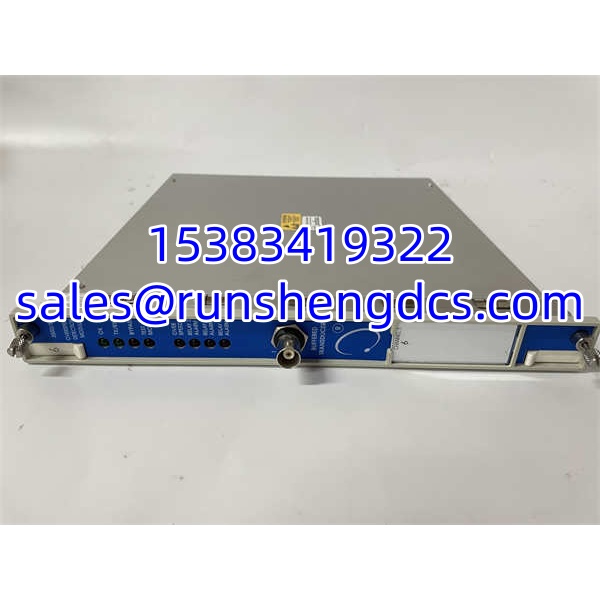

Description
Key Technical Specifications
| Parameter | Value |
|---|---|
| Module type | Overspeed Detection / Tachometer Monitor |
| Part number | 133388-01 |
| Typical ordering code | 3500/53-01-00 (verify per unit) |
| Compatible I/O module | 133396-01 Overspeed I/O Module |
| Sensor input | Proximity probe or magnetic pickup |
| Input voltage range | +10.0 V to -24.0 V (internally limited) |
| Input impedance | 20 kΩ |
| Power consumption | 8.0 W typical |
| Voting support | 2oo2 or 2oo3 (recommended for overspeed) |
| Redundant power requirement | Yes, 3500 rack must have redundant supplies |
| Buffered output | Front-panel coaxial connector |
| Buffered output impedance | 550 Ω |
| Sensor supply | -24 Vdc, max 40 mA |
| Recorder output | 4-20 mA proportional to speed |
| Recorder load | 0-600 Ω, 0-12 Vdc compliance |
| Relay type | SPDT, epoxy-sealed |
| Operating temperature | -30 to +65°C |
| Storage temperature | -40 to +85°C |
| Compliance | API 670, API 612 (overspeed protection) |
Product Introduction
Overspeed protection is one area where “close enough” does not work. The 3500/53 133388-01 sits in the Bently Nevada 3500 rack and converts a single proximity probe or magnetic pickup signal into a monitored speed measurement with configurable alarm and danger setpoints. It is not a general-purpose tachometer card. It is built for overspeed protection, and it is meant to be deployed in redundant 2oo2 or 2oo3 voting arrangements so that a single sensor or module fault does not cause a nuisance trip — or worse, a missed trip.
Each 3500/53 module consumes about 8.0 W and accepts inputs from Bently Nevada 3300, 7200, 3300 RAM, or compatible magnetic pickup sensors. It provides a buffered front-panel output for test equipment, a 4-20 mA recorder output, and SPDT relay outputs for trip logic. The rack must have redundant 3500/15 power supplies when the overspeed system is installed. Bottom line — this module is a protection component, not a diagnostic luxury. Treat procurement, testing, and replacement with the same discipline you would apply to a turbine trip relay.
QA/QC Transparency SOP
- Intake & Origin Verification — Confirm P/N 133388-01 on the module label and verify the full ordering code (e.g., 3500/53-01-00). Inspect the front coaxial connector, rear pins, and mating I/O module 133396-01 for corrosion, bent pins, or prior rework.
- Live Functional Testing — Install the 3500/53 into a verified 3500 rack with redundant 3500/15 power and a 3500/22M TDI or 3500/20 RIM. Apply a simulated proximity probe or magnetic pickup signal and confirm speed reading, OK LED, TX/RX communication, and relay response at configured setpoints.
- Electrical Parameter Tests — Verify -24 Vdc sensor supply (max 40 mA), 20 kΩ input impedance, 550 Ω buffered output impedance, and 4-20 mA recorder output into a 0-600 Ω load. Check relay continuity and coil operation.
- Firmware/Config Verification — Read module status and configuration via 3500 Rack Configuration Software. Confirm setpoints, alarm delays, voting mode, and that the module reports no internal faults to the frame interface.
- Final QC & Anti-Static Packaging — Record all test readings, label the unit with P/N and test date, place in ESD bag with desiccant, and ship in rigid packaging. Surplus units are sold as-tested, not as-new OEM.
Field Engineer Gotchas
- 133388-01 is not a standalone card. It requires the 133396-01 Overspeed I/O Module on the rear. Pulling the front module without confirming the I/O module type will leave you with an un-wirable channel.
- Redundant rack power is mandatory. The 3500/53 overspeed system requires redundant 3500/15 supplies. Installing it in a single-supply rack may pass bench checks but fails API 670 compliance and plant acceptance.
- Voting logic is configured in software, not wiring. A 2oo3 trip needs three 3500/53 channels, correct setpoints, and proper relay module configuration. Swapping one module without verifying the voting group can create a silent mismatch.
- Sensor type matters for low-speed testing. Magnetic pickups may not produce usable signal at very low roll speeds. If commissioning tests look unstable, check the sensor type and signal amplitude before blaming the module.
- Do not confuse 3500/53 with 3500/54. The 3500/53 is the overspeed monitor/tachometer. The 3500/54 is the electronic overspeed protection module with different architecture and I/O. They are not drop-in replacements.
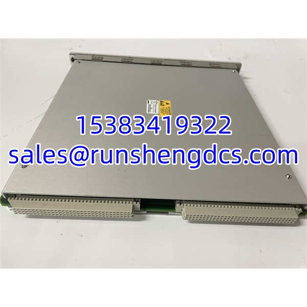
BENTLY 3500/53 133388-01
Application Scenarios
- Steam turbine overspeed protection: Provides the primary electronic overspeed channel in a 2oo3 voting group. Pain point: after an outage, one channel reads correctly but the other two disagree because the sensor gap or I/O module was changed.
- Centrifugal compressor trains: Monitors shaft speed for alarm and trip while feeding a 4-20 mA signal to the DCS. Pain point: the recorder output is loaded beyond 600 Ω, causing inaccurate speed indication in the control room.
- Gas turbine auxiliary drives: Used where API 612 and API 670 require independent electronic overspeed protection. Pain point: the rack lacks redundant power, so the overspeed function cannot be commissioned to spec.
- Large induced-draft fans: Provides speed monitoring and low-speed alarm during coast-down. Pain point: magnetic pickup signal drops out below 200 rpm, making zero-speed detection unreliable without sensor verification.
FAQ
Is 133388-01 a complete overspeed channel by itself?
No. It is the front monitor module. You also need the 133396-01 Overspeed I/O Module, correct sensor wiring, relay modules, and a 3500 rack with redundant power.
Can I use 133388-01 as a general-purpose tachometer?
It can measure speed, but it is engineered for overspeed protection. If you only need speed indication without trip logic, a 3500/50 tachometer module may be a better fit.
What sensors does it accept?
Bently Nevada 3300, 3300 16 mm HTPS, 7200, 3300 RAM proximity probes, or magnetic pickups. Verify the I/O module and sensor supply match your installed transducer.
Does it support 2oo3 voting?
Yes. Multiple 3500/53 modules can be configured for 2oo2 or 2oo3 voting. 2oo3 is the recommended arrangement for overspeed protection.
Is this module hot-swappable?
3500 monitor modules are generally hot-swappable, but removing an overspeed channel reduces voting redundancy. Coordinate with operations and verify the remaining channels are healthy before pulling it.
What is the difference between 3500/53 and 3500/54?
The 3500/53 is the overspeed monitor/tachometer module. The 3500/54 is a dedicated electronic overspeed protection module with different hardware and I/O. Do not substitute one for the other without a full engineering review.
Is surplus stock acceptable for overspeed protection?
Only if it has been tested in a live 3500 rack with verified speed simulation, relay operation, and configuration readback. Overspeed modules are protection devices. Treat them like trip relays, not spare I/O.